Wetted cavity
Identify the hydraulic geometry and surfaces that must be preserved. Separate flow passages from nonfunctional pockets and note inaccessible areas.
Fluid handling / Custom component supply
Pump bodies with machined shaft, seal and fluid interfaces, subject to application-specific material and pressure review.
A drawing, model, sketch or photograph is a useful starting point. Tell us what is known and what still needs work.
The component in service
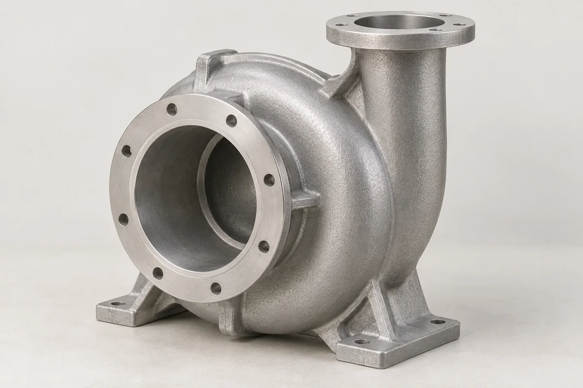
A pump housing guides fluid and supports the rotating or moving parts of the pump. Its suitability depends on the fluid, temperature, pressure and internal geometry, as well as the aluminum alloy. Share the pump type and wetted conditions early: a familiar housing shape is not enough to establish chemical compatibility or pressure capability.
Identify the hydraulic geometry and surfaces that must be preserved. Separate flow passages from nonfunctional pockets and note inaccessible areas.
Specify the relationship between shaft support, seal bore and cover face. Include the seal manufacturer’s installation requirements where available.
Define connection form, sealing method and fastening arrangement. Show the installed direction and clearance for hoses, fittings and maintenance tools.
Casting · machining · finish
Fluid compatibility and the pressure boundary must be reviewed before an alloy or casting route is accepted. Cored passages and heavy bosses can change both tooling and internal-quality requirements.
Machining allowances should support the required fits without unnecessarily opening subsurface discontinuities. Mark pressure-retaining zones and minimum finished sections on the review drawing.
Specify coatings or treatments only when compatible with the fluid and duty. Mask seal interfaces and agree cleaning, drying and port protection.
What can go wrong
These are review points for this type of component. The actual risks depend on the design, process and operating conditions.
Internal discontinuities, machining exposure, gasket support and assembly condition have different remedies. Define where leakage is unacceptable and how it will be assessed.
Misalignment, a damaged bore edge or unsuitable surface condition can affect the seal. Review insertion chamfers and the final machined condition.
Corrosion and erosion depend on the medium and operating conditions. Material acceptance needs an application review, not a general statement about aluminum.
WHAT TO MEASURE ON THIS PART
Use these features to build the inspection scope for your drawing. The illustrated geometry is an example, not a stocked or validated product.
Inspection methods & reporting →| Feature | Requirement to define | Check / evidence |
|---|---|---|
| Fluid boundary | Test conditions and allowable leakage | An agreed leak-test record; proof testing is separately specified if needed. |
| Seal features | Size, texture, edge condition and datum relationship | Dimensional and surface measurements before assembly. |
| Ports | Connection geometry and sealing face | Thread or dimensional checks appropriate to the specified connection. |
| Wetted cavity | Passage condition and cleanliness | Visual or other specified access method plus cleaning acceptance. |
Before the quotation
Unknown details can remain open in the first conversation. The next step is to make the assumptions clear.
Photos and basic dimensions are useful for the first discussion. State the fluid and duty, and identify whether a drawing or sample can follow.
No general coating claim can establish compatibility. The complete material and treatment system needs review for the actual fluid, temperature and service conditions.
PROCESS, MATERIAL & ACCEPTANCE
Start with what you have
Share a drawing, a few photos or the assembly problem you want to solve. If available, add quantities, material, finish and the interfaces that matter most. These help the review; they do not need to be complete to begin.
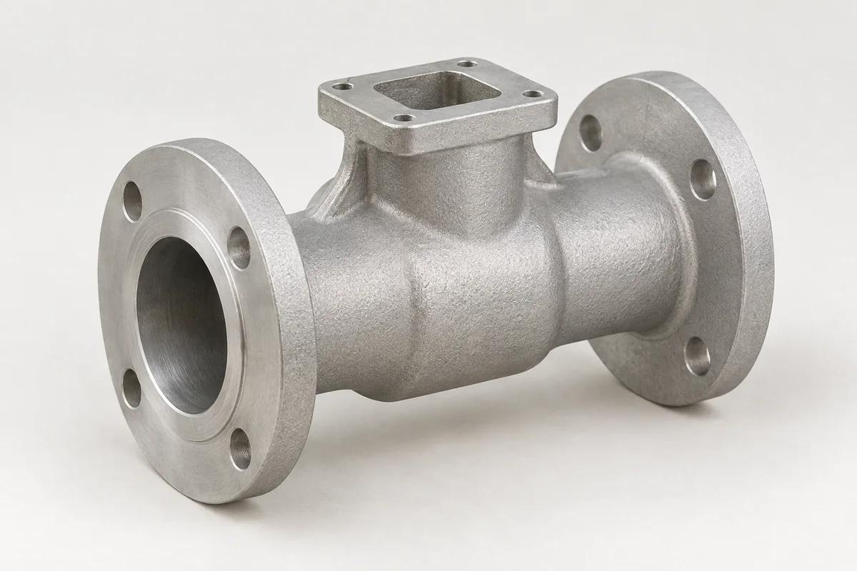
Valve and manifold bodies with port connections, internal passages and controlled sealing interfaces.
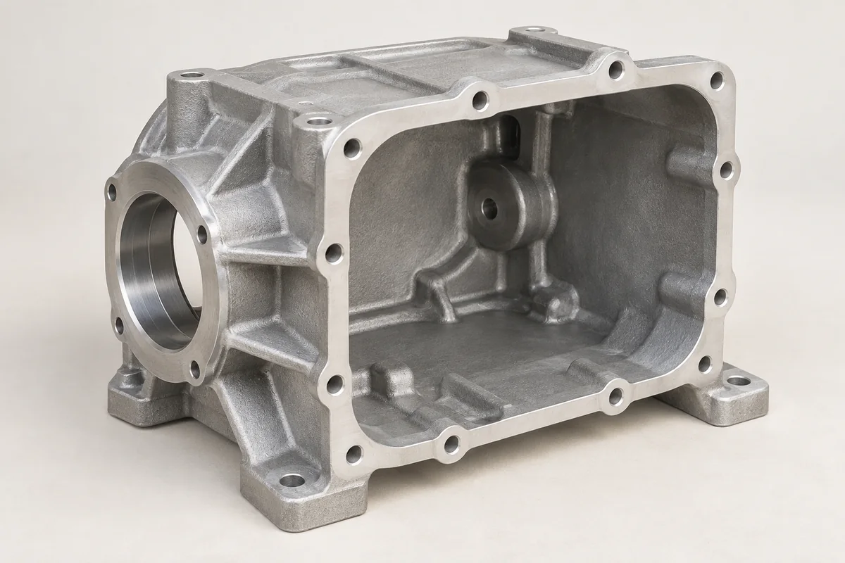
Explore this component ↗Gearbox bodies and covers with bearing locations, joint faces and lubricant interfaces reviewed as one assembly.
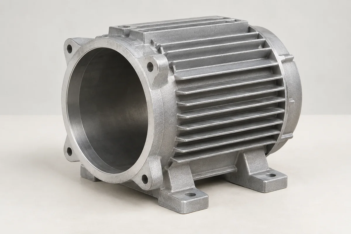
Explore this component ↗Motor frames with a stator interface, end-cover locations and mounting features developed around the complete rotating assembly.
Explore this component ↗