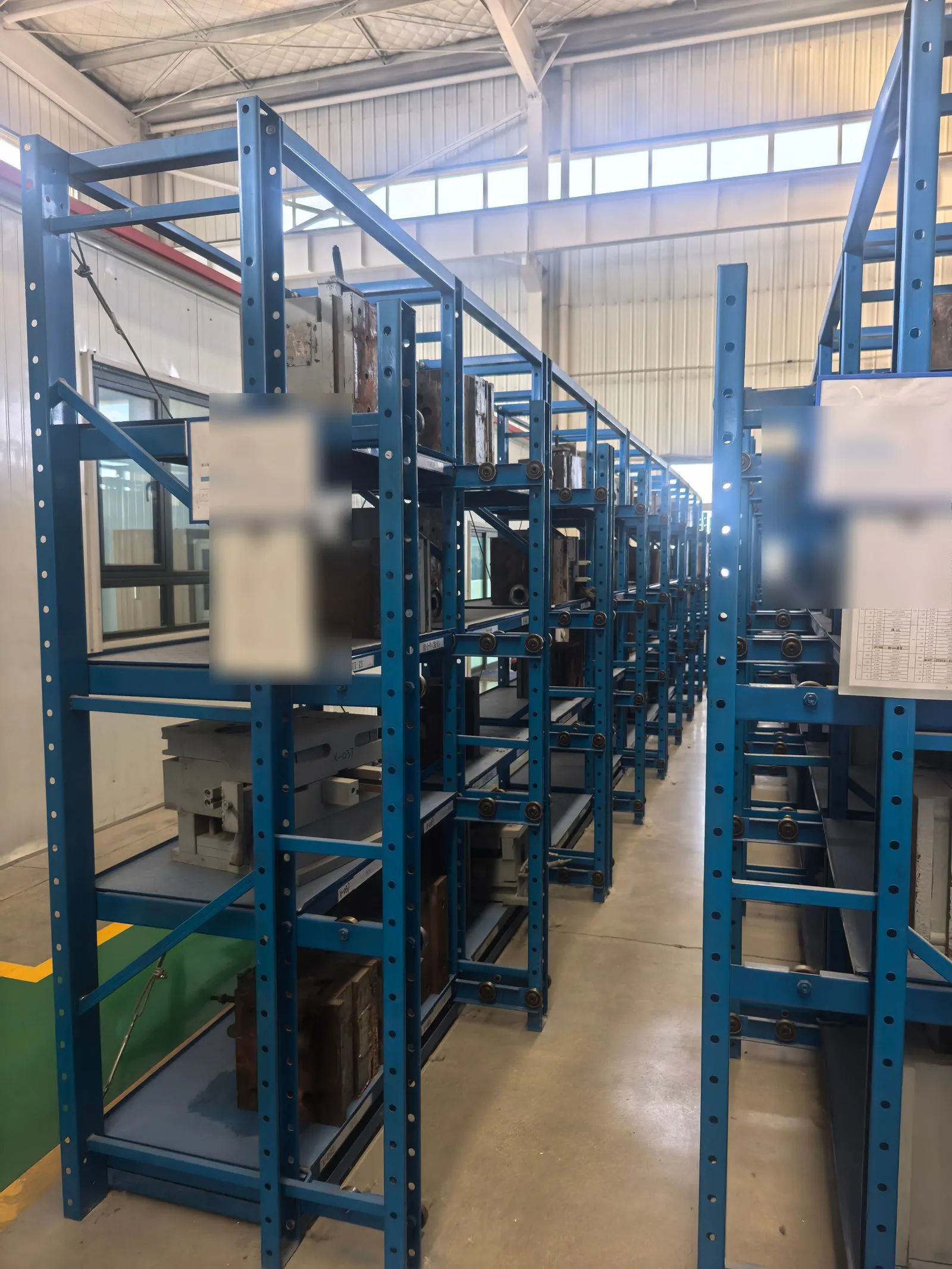
Rack locations and access
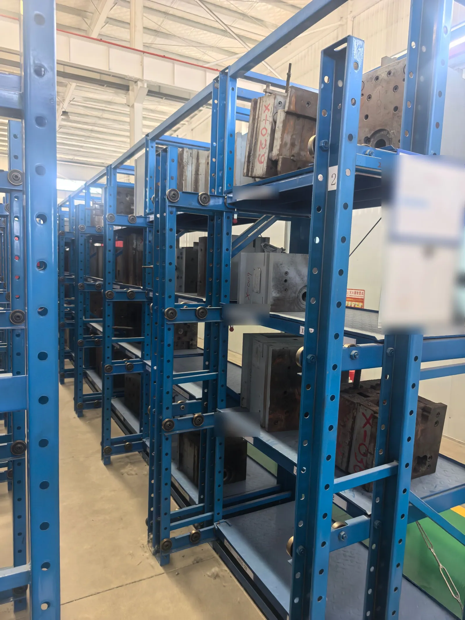
Rows of tooling racks provide storage positions and aisle access. Agree the tool identification, storage arrangements and retrieval process when planning repeat orders.
Capabilities / TECHNICAL GUIDE
A die determines which features cast cleanly, where secondary work begins and how later design changes affect cost. Develop the tool around the finished component and the intended production quantity.
Discuss your part ↗Drawings, sketches, photographs or an early specification are welcome.
PROCESS PLANNING
Start with the release direction and the surfaces that matter in assembly. A convenient parting line for the tool can be an inconvenient seam on a gasket face or visible exterior.
TOOLING / STORAGE & IDENTIFICATION
The storage location is one part of the picture. A useful tooling record also connects the tool reference to the drawing revision, trial history and agreed maintenance scope.
TOOL DEVELOPMENT
Tooling is developed around the part, its production volume and the dimensions that need to be controlled.
Identify the parting line, draft, undercuts and surfaces that will be machined. Confirm which dimensions belong to the casting and which will be finished later.
Plan inserts, slides, ejection and machining allowance around the part geometry. Review filling and feeding where the design requires it.
Check trial castings against the drawing. Record dimensional issues, flash and filling defects, then agree corrections before the next sample review.
Agree the sample revision and inspection results before releasing the production run. Tool changes need to remain linked to the current drawing.
Have a drawing or an existing part? Send what you have. We can review the remaining specifications with you.
Discuss your part ↗01 / Capabilities
Review draft by pull direction, including ribs, bosses and internal pockets. Undercuts may require moving slides or a change in geometry. The decision affects tool complexity, witness marks and maintenance access; a slide is not a cost-free substitute for revising a feature.
Thin-to-thick transitions, isolated heavy bosses and long flow paths need attention together. A uniform nominal wall with supported bosses can be easier to fill and cool than a solid mass added around a threaded hole. Confirm the parting line, gates, overflows and ejector contact zones against both the drawing and the cosmetic map.
02 / Capabilities
Leave machining allowance where faces and bores will be cut, while checking that cast variation cannot remove that allowance locally. Provide stable locating and clamping regions that will remain accessible after trimming.
A replaceable insert may make sense around a feature expected to change or wear, but it introduces its own interface and thermal behavior. Identify likely engineering revisions before committing the cavity design; late changes can require welding, an insert or replacement steel.
03 / Capabilities
Inspect trial parts after the required secondary operations. Record cavity identity, drawing revision, sample condition and the open issues. Distinguish a dimensional correction in the tool from a machining fixture adjustment or a process change.
Approve the revised samples against agreed evidence before production release. The tooling agreement should identify ownership, storage, maintenance responsibilities, modification approval and any transfer conditions. Tool life and replacement terms belong in the project quotation, not a generic website promise.
CAPABILITIES / PROJECT DETAILS
| Subject | Technical definition | Useful evidence |
|---|---|---|
| Release geometry | Draft, undercuts, slides and ejector access | Marked model review with proposed witness-mark locations |
| Functional surfaces | Machining allowance and fixture access | Trial casting plus machined sample results |
| Tool revisions | Cavity/insert change and affected features | Revision record and repeat sample scope |
| Commercial scope | Ownership, upkeep, storage and transfer | Written tooling scope with the quotation |
The quotation and agreed inspection plan establish which records and checks apply to the project.
COMMON QUESTIONS
Yes, the discussion can start there. Geometry capture and drawing development may be needed before the cavity can be released, and that work should be identified in the proposal.
No. Record the approved revision, finish, inspection scope and permitted deviations. A later alloy, process or geometry change may require another review.
RELATED GUIDES
Send the part’s purpose, available files and the question you need to resolve. Material, process and inspection details can be developed during the review.