Tooling & DFM
Review parting line, draft direction, slides, gate and overflow locations, ejection marks and machining allowance. Keep gates and ejector marks away from defined cosmetic and sealing zones where the tool design permits.
CAPABILITIES / Aluminum die casting
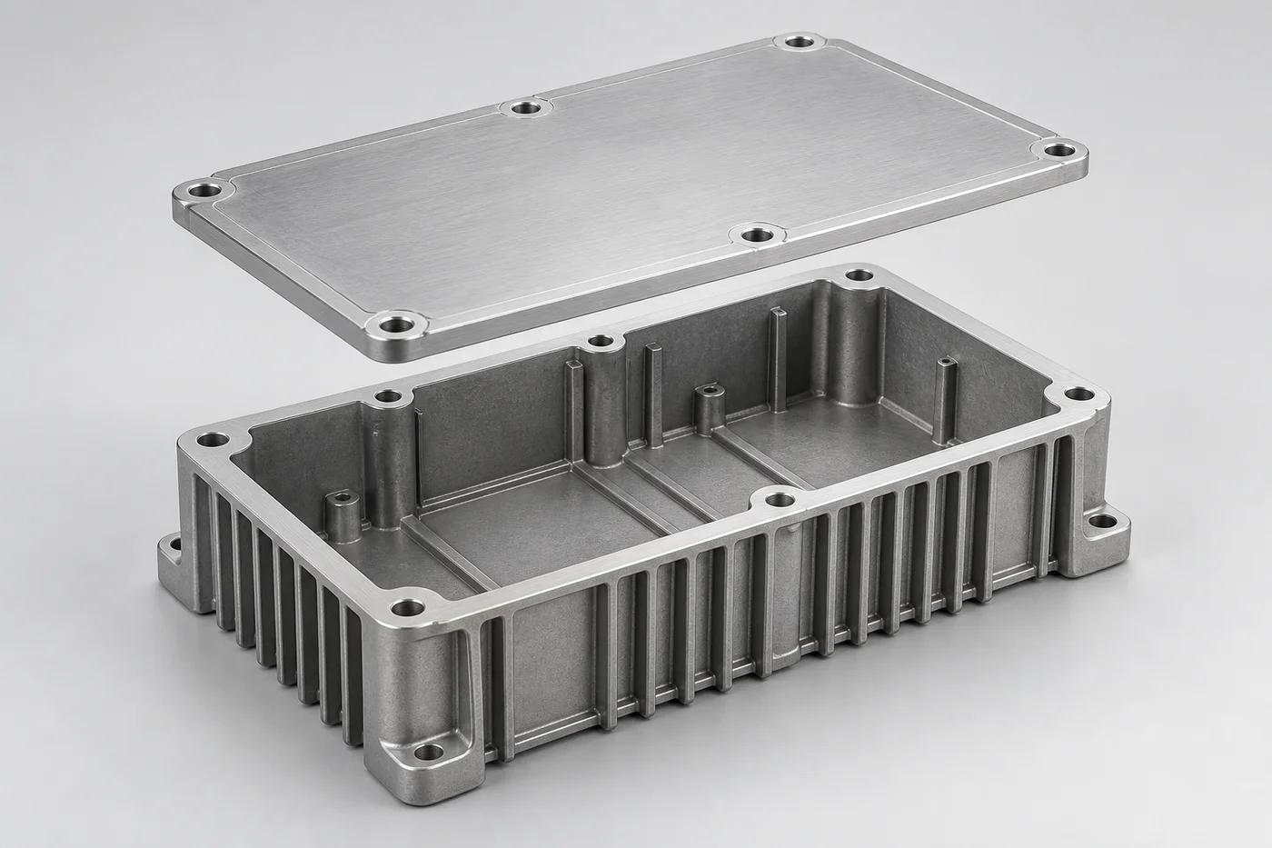
Custom aluminum housings, end caps and brackets with cast ribs, bosses and mounting geometry. The manufacturing route separates economical cast features from the faces, bores and threads that need machining.
Request a technical quotation ↗See the manufacturing steps ↓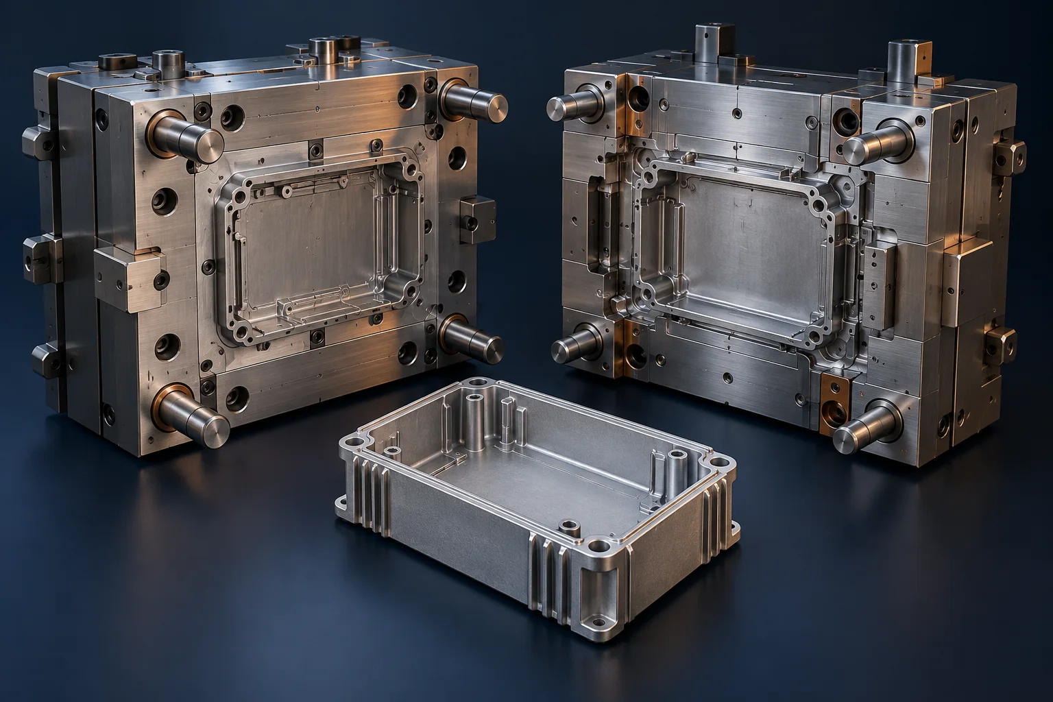
PROCESS SELECTION
A useful route for repeat production where dedicated tooling can replace substantial machining from solid stock. Tooling cost, annual demand, geometry and finishing determine the commercial fit.
FROM DRAWING TO FINISHED PART
Review parting line, draft direction, slides, gate and overflow locations, ejection marks and machining allowance. Keep gates and ejector marks away from defined cosmetic and sealing zones where the tool design permits.
Identify the alloy and material condition. Establish the required melt handling and die thermal condition for the selected process.
Control the shot sequence, filling conditions, pressure stage and die cooling through the process setup. Changes to these variables can affect filling, trapped gas and dimensional stability.
Remove runners, flash and accessible burrs. Locate the casting consistently before machining bearing seats, sealing faces, threads or mounting pads.
Check the specified dimensions, surface condition and any defined internal-quality or leakage requirements. Protect finished faces and threads during shipment.
WHAT NEEDS CONTROL
The drawing and order define the applicable controls; inspection methods are selected for the requirement rather than applied indiscriminately.
| Feature / risk | Production consideration | Verification method |
|---|---|---|
| Porosity at a machined face | Review local section changes, gating/venting and process settings; examine the location relative to the machined allowance. | Defined porosity inspection; leakage check separately if required. |
| Cold shuts or incomplete fill | Review flow path, thin sections and process thermal conditions. | Visual examination and specified defect criteria. |
| Flash & parting-line mismatch | Review tool condition, shut-offs and trimming access. | Visual or gauged limits at functional and cosmetic areas. |
| Distortion or unstable fit | Review cooling, ejection, support and machining location. | Datum-based dimensional inspection after the required operations. |
DETAILS THAT CHANGE THE QUOTATION
State the applicable alloy standard and grade. Names such as ADC12, A380 and EN AC-46000 are not blanket interchangeable specifications.
Mark close fits and geometric controls individually. Do not apply a machining tolerance indiscriminately to every as-cast feature.
Select the finish together with the alloy and cosmetic requirement. A decorative anodized appearance cannot be assumed for every casting alloy.
SAMPLE & PRODUCTION PACKAGE
Tooling and machining scope, sample-stage dimensional requirements, surface acceptance and the production inspection package.