Locate the blank
Choose repeatable support and clamping points. Check that casting variation leaves sufficient material at every machined feature.
CAPABILITIES / CNC machining
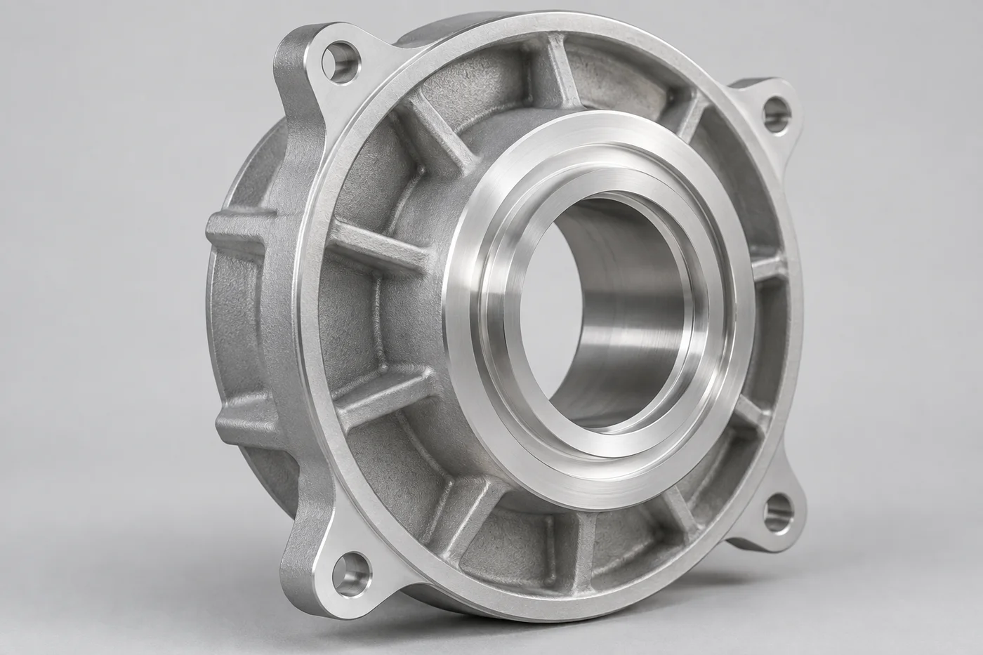
Finish machining for aluminum castings and custom machined components. The focus is on bearing seats, flange faces, connector openings, mounting patterns and threaded interfaces.
Request a technical quotation ↗See the manufacturing steps ↓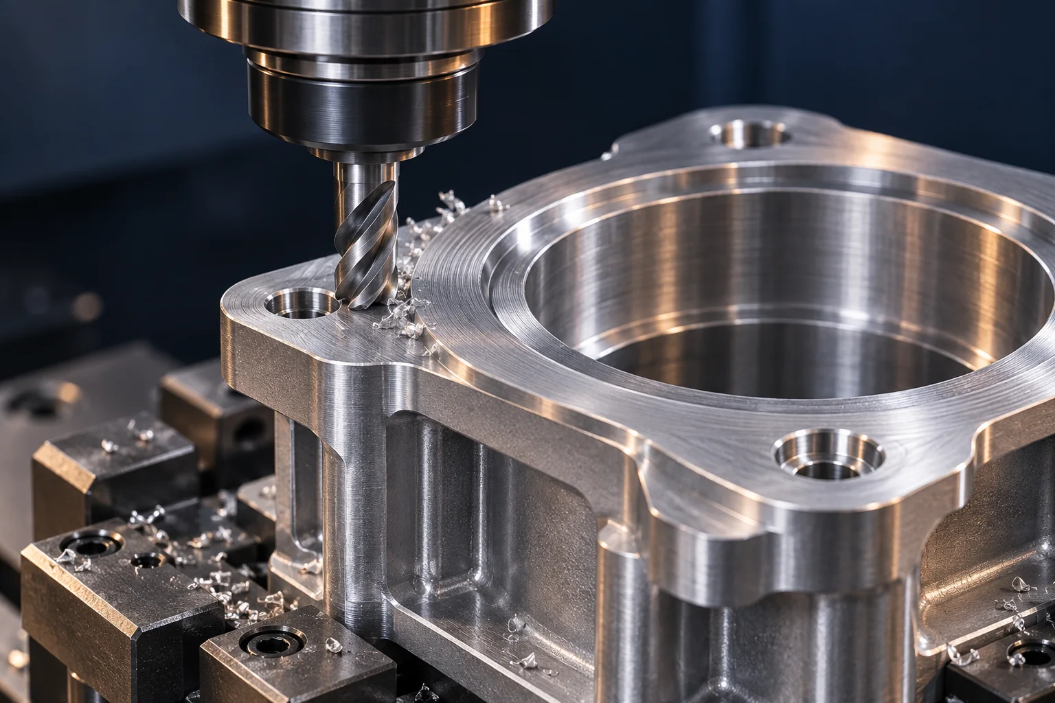
PROCESS SELECTION
Machining from stock can suit development or lower quantities; machining a casting can reduce stock removal in repeat production. Compare both routes using the actual geometry, material and quantity.
FROM DRAWING TO FINISHED PART
Choose repeatable support and clamping points. Check that casting variation leaves sufficient material at every machined feature.
Machine the planned datums and locate subsequent features from them. Avoid treating unrelated setups as though they automatically share the same reference.
Mill faces and pockets; drill, bore or ream holes as appropriate; produce threads to the drawing. Sequence related features to control their relationship.
Remove burrs at cross-holes, thread entries and edge breaks. Remove chips and residues from blind holes and internal cavities.
Measure critical sizes and geometric controls after the relevant operations. Account for finishing or masking before accepting a fit.
WHAT NEEDS CONTROL
The drawing and order define the applicable controls; inspection methods are selected for the requirement rather than applied indiscriminately.
| Feature / risk | Production consideration | Verification method |
|---|---|---|
| Bearing fit | Control bore size and the specified form and datum relationship. | Suitable bore measurement; CMM for defined geometric relationships. |
| Flange or gasket face | Manage clamping distortion and tool marks; identify required flatness and texture. | Flatness evaluation and surface-texture measurement where specified. |
| Hole-pattern position | Reference the specified datums; review fixture and setup repeatability. | CMM or a suitable approved functional fixture. |
| Thread acceptance | Define thread standard, class, useful depth and coating condition. | Specified GO/NO-GO thread gauge and depth check. |
DETAILS THAT CHANGE THE QUOTATION
A 3D model establishes geometry; the controlled drawing establishes tolerances, datums, threads, finish and acceptance notes.
Specify required texture on functional faces instead of requesting a uniform fine finish everywhere. Measurement direction and cutoff matter when texture is controlled.
Include counterbores, fastener access and mating-part clearances. A dimensionally correct part can still be difficult to assemble.
SAMPLE & PRODUCTION PACKAGE
Machining scope, critical-characteristic list, dimensional report requirements and cleaning or packaging instructions.