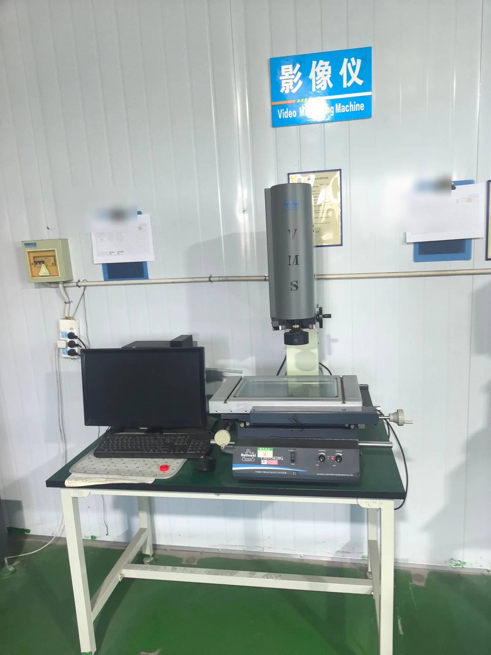
Visible profiles and edges
Optical measurement uses a visible image of the feature. Edge definition and lighting matter; it does not show the internal condition of the casting.
Quality / TECHNICAL GUIDE
Measure the features that control assembly, using the drawing’s reference system and the part’s required final condition. A useful result records what was measured and how it was accepted.
Discuss your part ↗Drawings, sketches, photographs or an early specification are welcome.
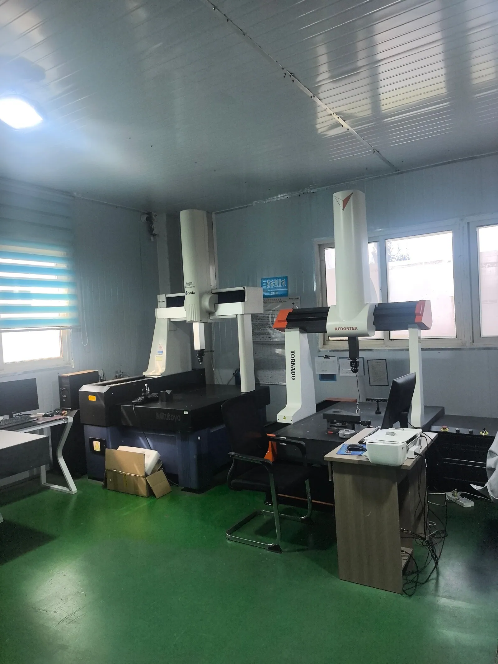
CHOOSING THE INSPECTION
Choose the measurement from the requirement. Bore diameter, roundness and bore position are separate characteristics even when they refer to the same hole.
DIMENSIONAL INSPECTION / EQUIPMENT
A coordinate measurement and an optical profile measurement answer different questions. Establish how the part is located and which drawing characteristic is being evaluated.
01 / Quality
Identify the controlled drawing revision and number the reported characteristics. Review the datum features, material-condition modifiers where present and the condition in which the component is restrained or free.
A CMM alignment should reflect the drawing’s datum system. A convenient best-fit alignment can conceal the relationship the drawing actually controls. Probe access, point distribution and fixture support affect what the measurement represents.
02 / Quality
Bore gauges and internal measuring tools support diameter checks at defined depths and directions. Micrometers support suitable outside-size checks. GO/NO-GO thread gauges assess the specified thread acceptance, with usable depth checked separately where required.
Calipers are useful for appropriate general sizes but do not replace every precision measurement. Instrument selection must consider resolution, uncertainty, accessibility and surface condition. A CMM alone is not a complete strategy for texture, thread acceptance or every form requirement.
03 / Quality
Clean and stabilize the part as appropriate to the measurement. Clamping can distort thin walls; temperature differences can change size readings. Record the final condition, including machining and coating, when those operations affect acceptance.
A report should connect each characteristic to nominal value, limits, actual result, method and disposition. If a result is outside limits, retain the deviation reference and affected sample identity instead of reporting only an overall pass.
QUALITY / PROJECT DETAILS
| Subject | Technical definition | Useful evidence |
|---|---|---|
| Bearing bore size | Suitable internal measurement at defined locations | Actual readings; form control separately if specified |
| Hole-pattern position | CMM or approved functional method | Datum alignment and evaluated characteristic |
| Gasket face | Flatness and specified texture checks | Part restraint and measurement condition |
| Threads | Specified GO/NO-GO gauge and depth check | Thread standard/class and acceptance result |
The quotation and agreed inspection plan establish which records and checks apply to the project.
COMMON QUESTIONS
No. Use methods suitable for each characteristic. The inspection plan can combine coordinate measurement, direct size readings and functional gauging.
Send the available drawing and assembly context. The reference surfaces and critical relationships can be discussed before the inspection plan is finalized.
RELATED GUIDES
Send the part’s purpose, available files and the question you need to resolve. Material, process and inspection details can be developed during the review.