Bearing locations
Show shaft center distances, bearing shoulders and the datum relationships between bores. Distinguish locating features from clearance pockets.
Motors & drives / Custom component supply
Gearbox bodies and covers with bearing locations, joint faces and lubricant interfaces reviewed as one assembly.
A drawing, model, sketch or photograph is a useful starting point. Tell us what is known and what still needs work.
The component in service
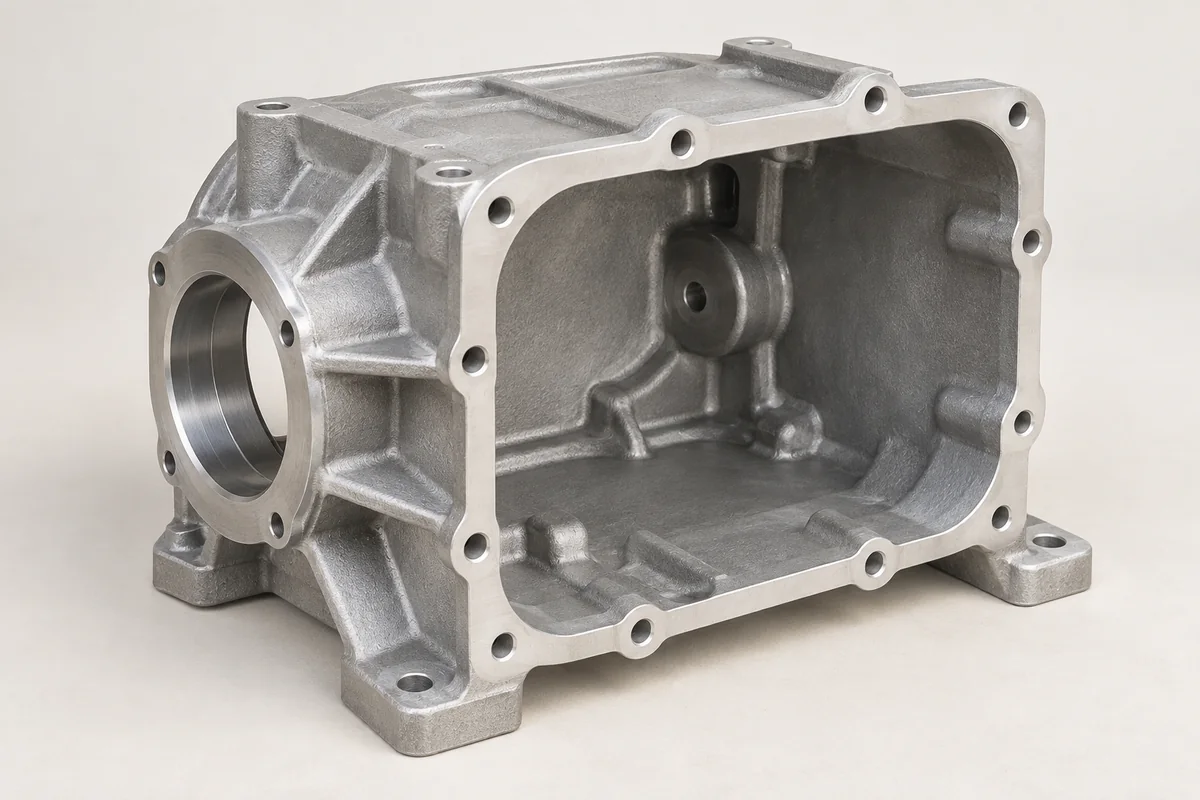
A gearbox housing locates shafts and bearings while containing lubricant and supporting the mounting loads. Shaft spacing, bearing alignment and cover location matter together: each affects how the internal assembly fits and how the gear system operates. The external shape is only the starting point; provide the bearing arrangement, split line and service access wherever they are available.
Show shaft center distances, bearing shoulders and the datum relationships between bores. Distinguish locating features from clearance pockets.
Define dowels or other location features, gasket or sealant approach, joint flatness and bolt access. State whether the two pieces are interchangeable or accepted as a matched assembly.
Locate fill, drain and breather ports for the installed orientation. Include tool access and internal passages that must remain open after machining.
Casting · machining · finish
The cavity, parting direction and internal features influence tooling and core requirements. Deep pockets and abrupt thick sections deserve an early manufacturing review.
Use the bearing layout to establish datums and operation sequence. Where assembly machining is proposed, agree how parts are identified and replaced in service.
Specify internal and external finish separately. Protect bearing seats, seal lands and lubricant passages; agree cleaning and protection before packing.
What can go wrong
These are review points for this type of component. The actual risks depend on the design, process and operating conditions.
An acceptable individual bore size does not prove that shaft spacing and alignment meet the design. Review the complete geometric relationship.
Joint damage, local porosity exposed by machining, seal installation and fastener loading can all contribute. A leak specification needs a defined boundary and test setup.
Burrs or retained chips at intersecting holes may enter the assembly. Cleaning access and passage checks belong in the machining plan.
WHAT TO MEASURE ON THIS PART
Use these features to build the inspection scope for your drawing. The illustrated geometry is an example, not a stocked or validated product.
Inspection methods & reporting →| Feature | Requirement to define | Check / evidence |
|---|---|---|
| Shaft system | Bore size, position and relationship | A datum-based report for the specified bearing features. |
| Joint faces | Flatness, locating dowels and bolt pattern | Face and position measurements; agreed joint condition. |
| Oil boundary | Leak acceptance where required | Specified medium, pressure, duration, fixture and allowable leakage. |
| Internal passages | Burrs and residual contamination | Passage inspection and the agreed cleanliness evidence. |
MACHINING & MEASUREMENT
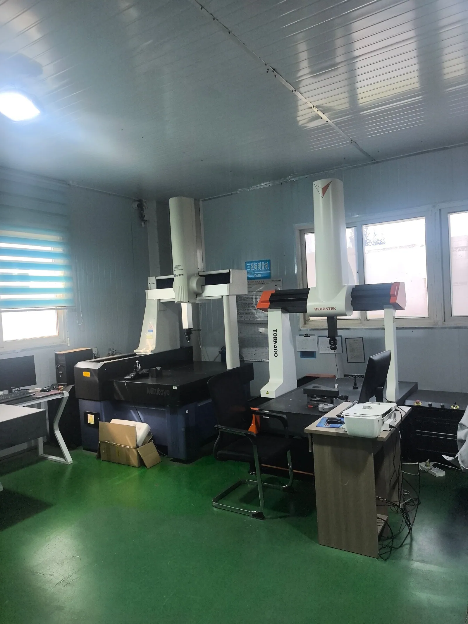
Our inspection-room photograph shows the CMM equipment behind dimensional verification. For a gearbox housing, the useful report relates bearing bores, shoulders and joint faces to the drawing's datums.
A bore diameter alone cannot show whether two shafts will be correctly located. The sample inspection scope should identify the bore relationship, locating features and the condition in which the housing is measured.
This is a photograph of inspection equipment, not a measurement result for the illustrated gearbox housing.
Before the quotation
Unknown details can remain open in the first conversation. The next step is to make the assumptions clear.
That depends on the locating and machining strategy. Share both parts where possible so interchangeability, assembly machining and identification can be discussed.
No. Leak testing addresses the specified boundary and conditions. Gearbox running, noise, temperature and durability validation belong to a separate assembly plan.
PROCESS, MATERIAL & ACCEPTANCE
Start with what you have
Share a drawing, a few photos or the assembly problem you want to solve. If available, add quantities, material, finish and the interfaces that matter most. These help the review; they do not need to be complete to begin.
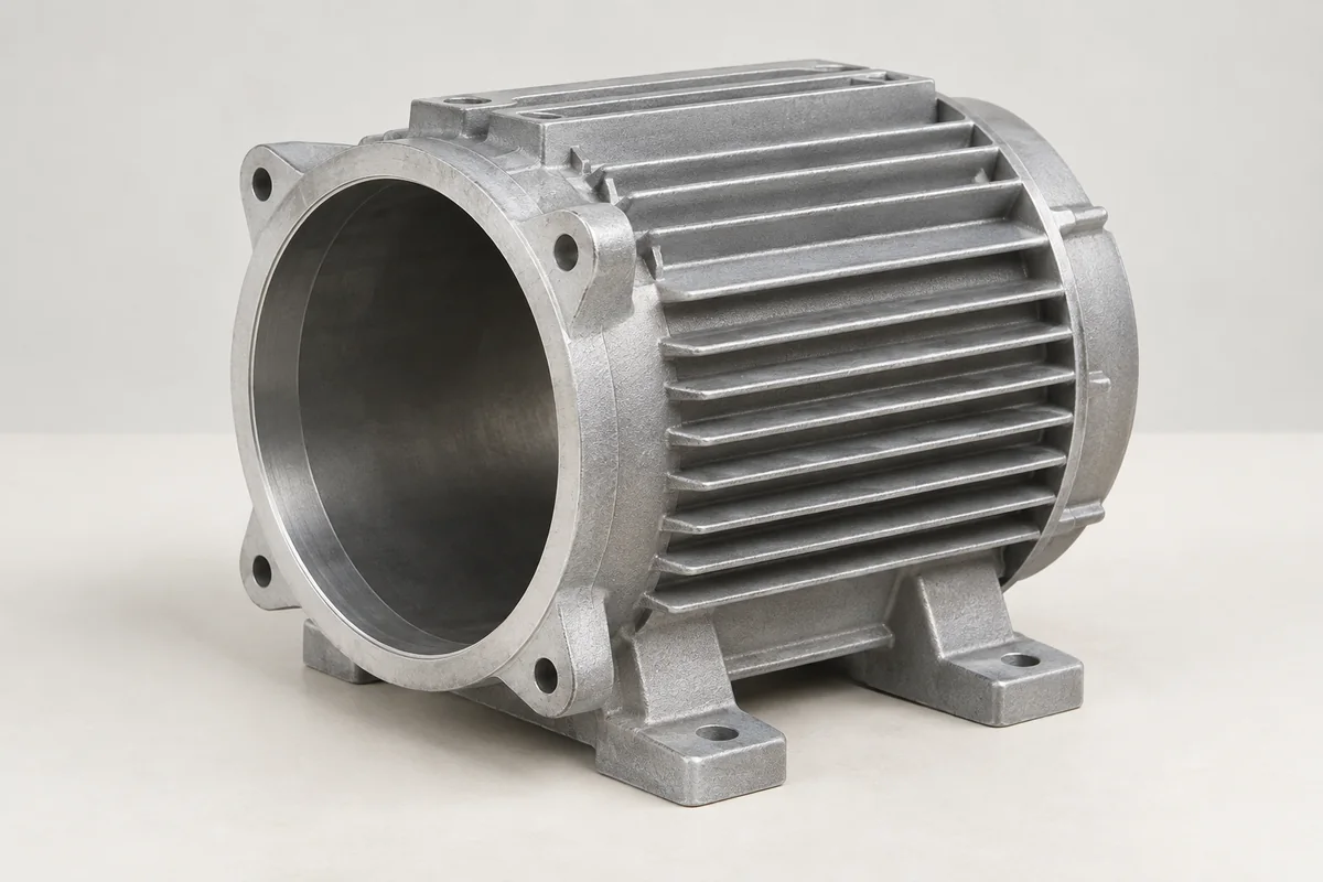
Motor frames with a stator interface, end-cover locations and mounting features developed around the complete rotating assembly.
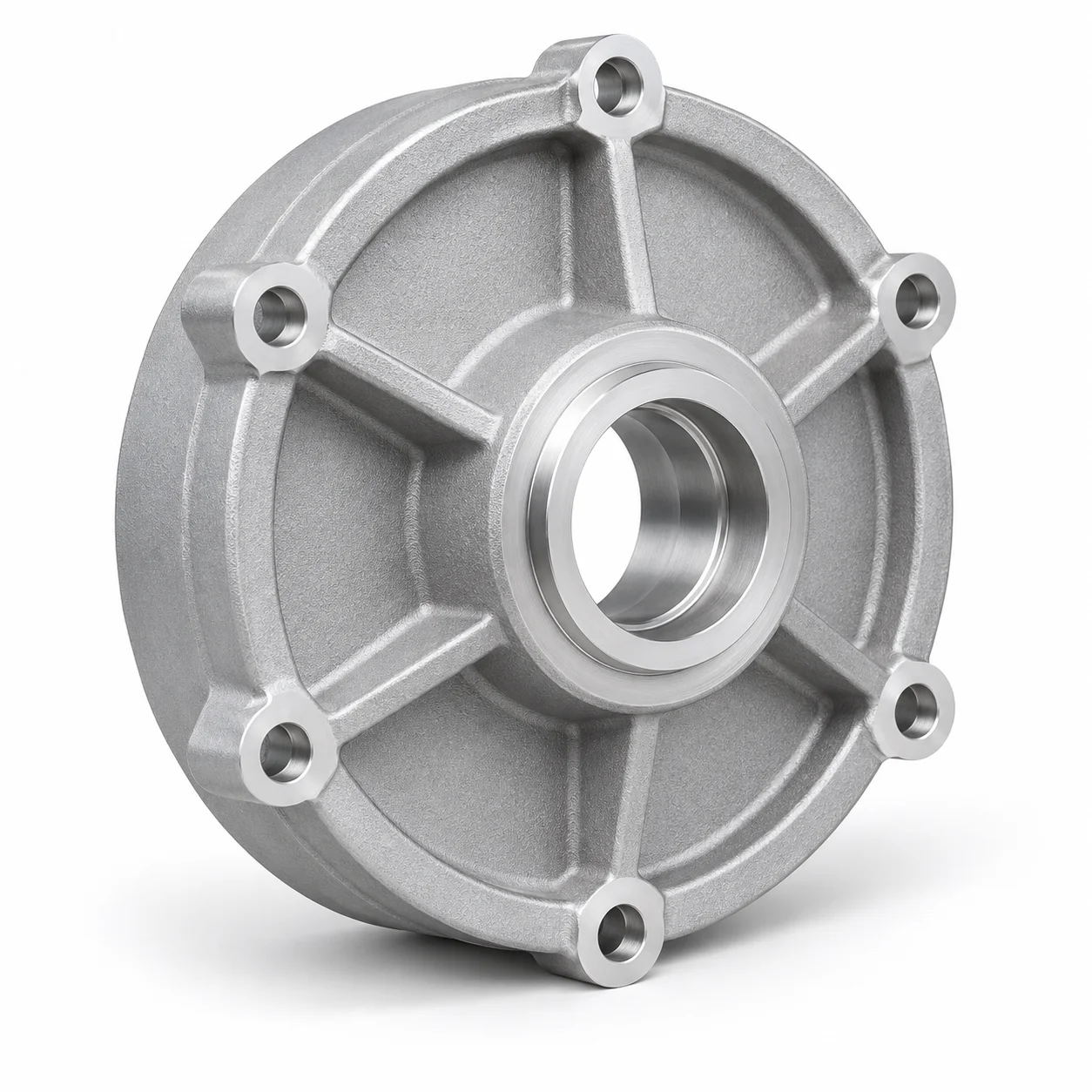
Explore this component ↗Drawing-controlled end caps for motor and equipment assemblies.
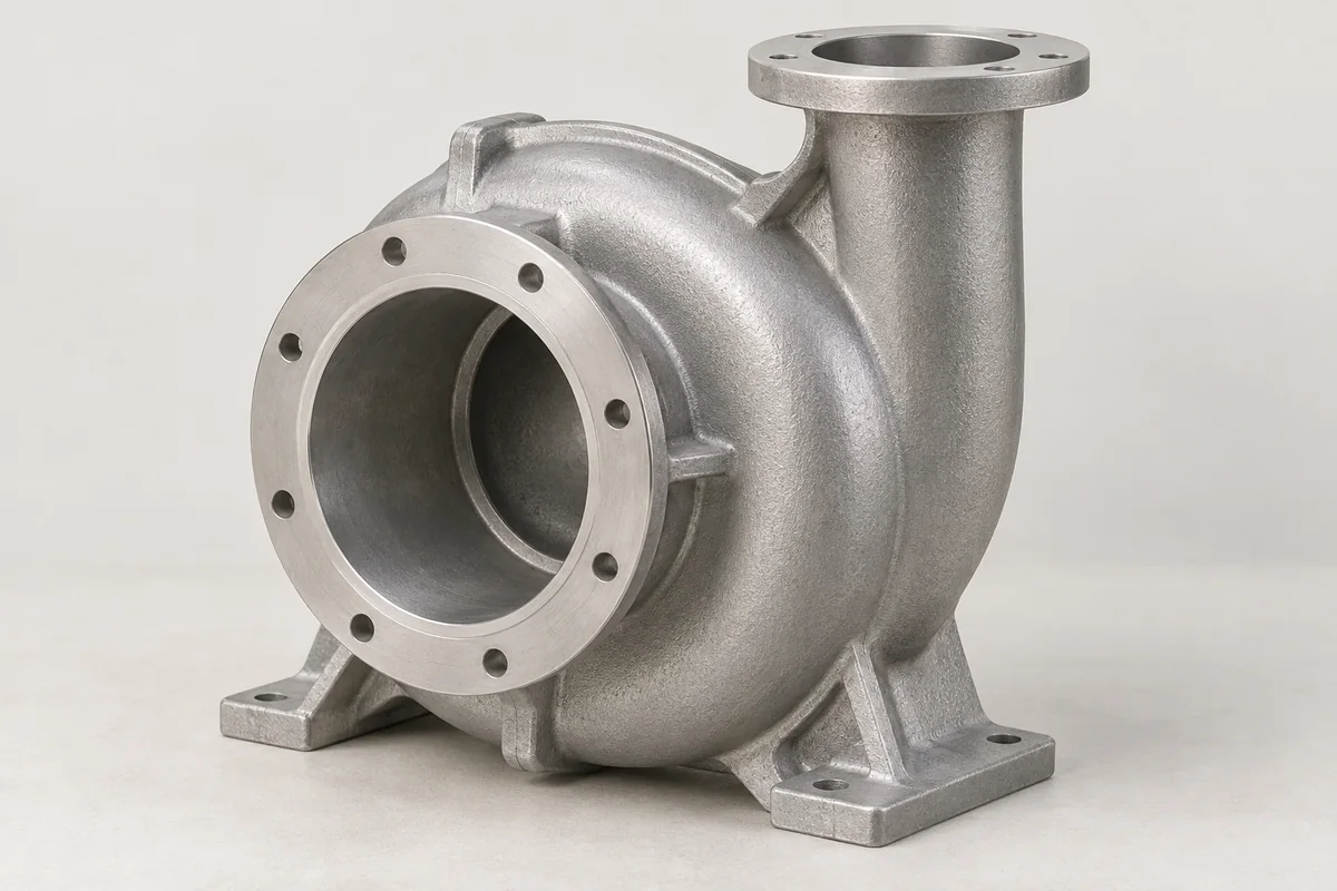
Explore this component ↗Pump bodies with machined shaft, seal and fluid interfaces, subject to application-specific material and pressure review.
Explore this component ↗