Key interfaces
Bearing bores, axial locating faces, concentric features and bolt patterns.
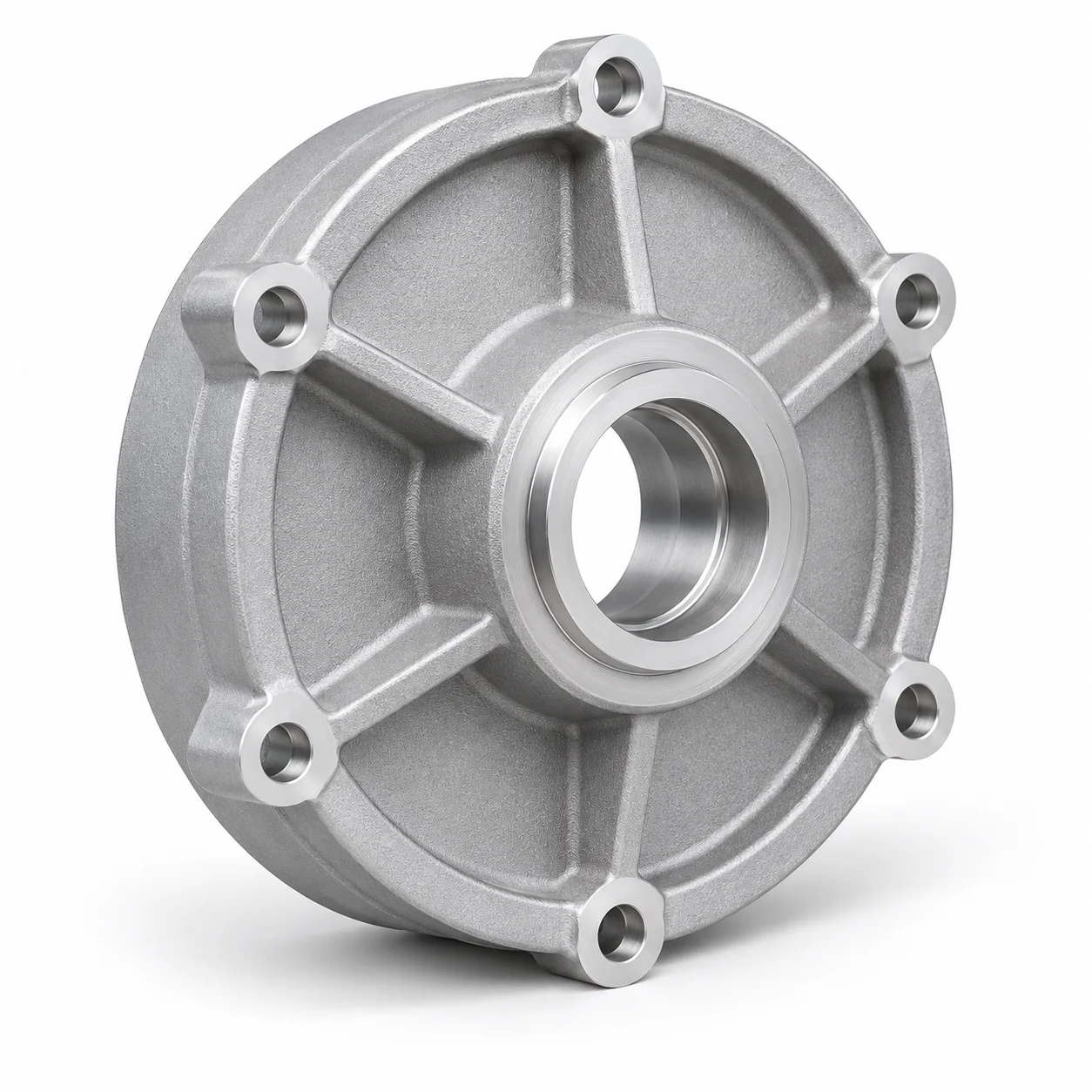
Custom aluminum end caps for motor and equipment assemblies, with drawing-defined bearing seats, flange interfaces and mounting features.
For a useful quotation: share your drawing, alloy, quantity and required finish.
Cast near-net geometry → machine bearing and flange features → finish and inspect
 Component illustration
The supply scope combines the manufacturing route, inspection requirements and delivery requirements for your component.
| Finish | Specified per drawing; masking agreed before processing |
|---|---|
| Inputs | Controlled drawing, model, quantity and critical dimensions |
| Status | Illustrative concept, not a catalog component |
| Process | Casting and secondary machining, as applicable |
| Material | Aluminum alloy, subject to review |
| Inspection | Project-specific dimensional and documentation scope |
| Interfaces | Mounting face, locating diameters and shaft or bearing interfaces |
Pricing, tooling, quantities and lead time are quoted for the individual project.
Bearing bores, axial locating faces, concentric features and bolt patterns.
Specify bore and mating-face condition separately from the exterior finish. Confirm masking requirements before coating.
Identify fit requirements and datum relationships. Agree how bores, mounting faces and related critical features will be measured.
Motor end caps connect the motor structure to critical locating and rotating interfaces. Our project review focuses on the relationship between the mounting face, locating diameter, bearing interface and shaft opening. Drawing-controlled fits and geometric requirements guide the machining route and the inspection setup.
VelnoCast brings aluminum casting, CNC machining and finishing into a coordinated component supply process. We review recurring quantities, geometry and functional requirements to define a suitable route. For cast components, the review covers draft, parting direction, wall transitions and machining stock. For machined components, it covers access, fixturing and the relationship between critical features.
Identify the features that control fit, alignment, sealing and assembly. Separate these from cosmetic requirements so each can be addressed with an appropriate production and inspection method. Drawing revision, material specification and reference datums provide the common basis for the quotation, sample review and production record.
Specify visible areas, coating requirements and interfaces to be masked. Threads, grounding contacts and sealing faces need particular attention when surface treatments are involved. Include deburring, cleanliness and packaging expectations in the drawing package, especially for components that enter an assembly directly.
Our quality review connects the important characteristics to an inspection method and the records required for acceptance. Discuss sample approval, dimensional reporting, material documentation and batch identification before production release. Agreed acceptance criteria govern the specific project.
Send the current drawing, a compatible 3D model where available, the required alloy and initial and annual quantities. Include target milestones and open engineering questions. Our team uses these inputs to clarify the technical scope and prepare a project-specific proposal.
WHAT TO MEASURE ON THIS PART
Use these features to build the inspection scope for your drawing. The illustrated geometry is an example, not a stocked or validated product.
Inspection methods & reporting →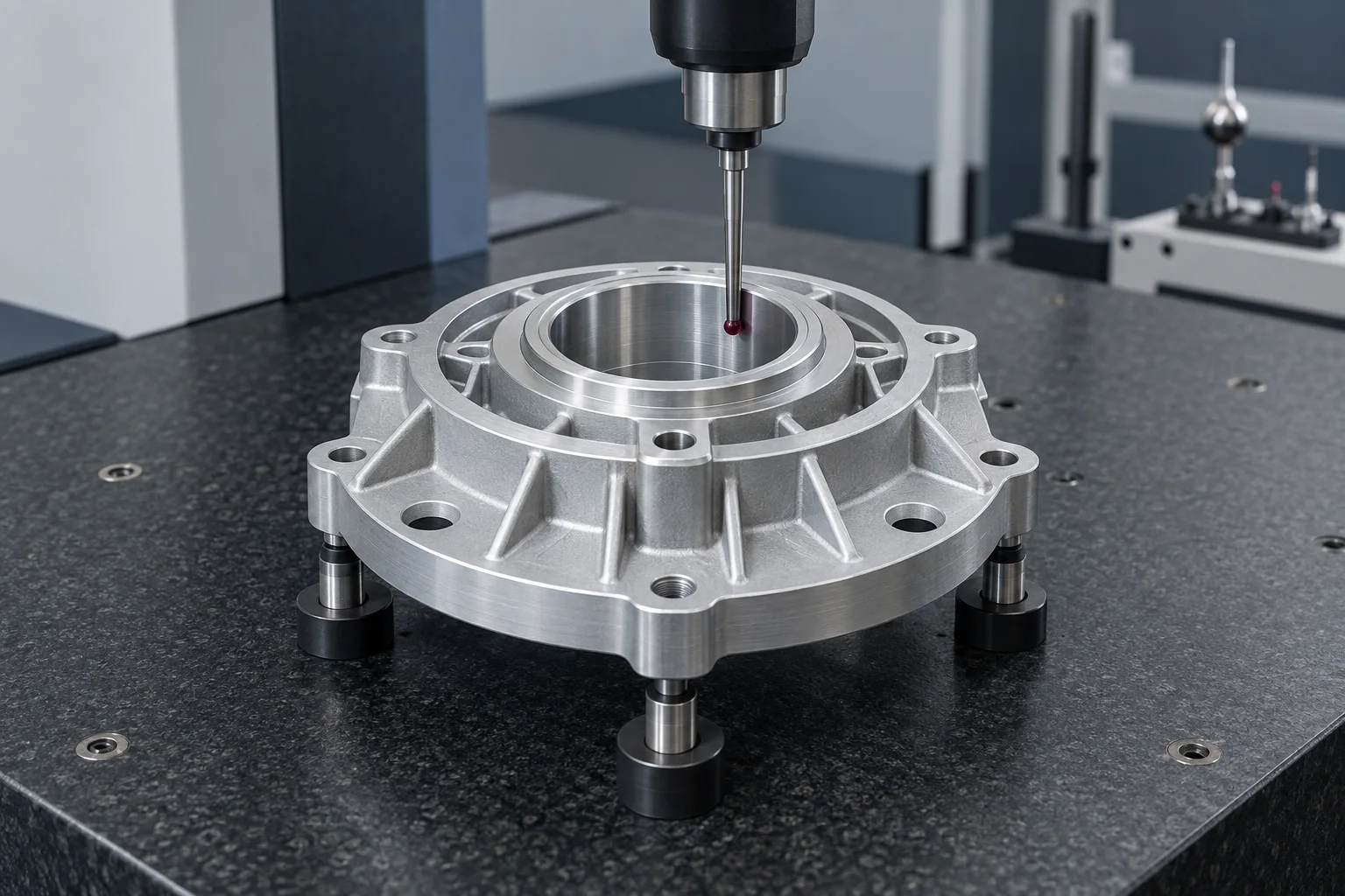
| Feature | Requirement to define | Check / evidence |
|---|---|---|
| Bearing seat | Bore size, form and required surface texture. | Suitable bore measurement, drawing-defined form evaluation and texture check. |
| Flange / bore relationship | Perpendicularity, position or runout as actually specified. | CMM or suitable geometric measurement using the specified datum system. |
| Bolt pattern | Hole size, location, counterbore and fastener clearance. | Coordinate or functional-gauge inspection appropriate to the tolerance. |
| Final condition | Clean bores, burr-free edges and correctly masked fits. | Visual and dimensional checks after operations that can affect acceptance. |
Send your 2D drawing and 3D model where available. Add target quantities and highlight critical dimensions or any requirements still open to discussion.
Download the RFQ checklist ↓Custom dimensions. Project-specific material, finish and inspection.
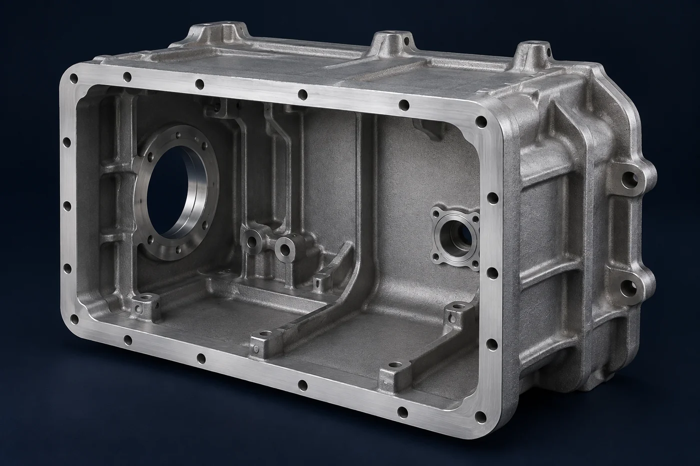
Send your RFQ ↗View quality & documentation →Custom housings with drawing-defined sealing, connector and mounting interfaces.
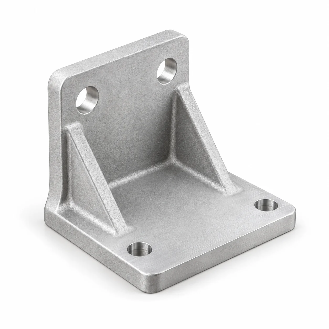
Cast mounting supports with machined pads, holes and threads for equipment integration.
Component examples show a complete brief. Simulated inputs are labeled and do not represent customer delivery records.
AI-generated illustrations of components and processes.