Stator seat
Identify the stator envelope, retention method, axial stop and assembly temperature assumptions. Do not substitute a generic bore tolerance for the fit your motor design needs.
Motors & drives / Custom component supply
Motor frames with a stator interface, end-cover locations and mounting features developed around the complete rotating assembly.
A drawing, model, sketch or photograph is a useful starting point. Tell us what is known and what still needs work.
The component in service
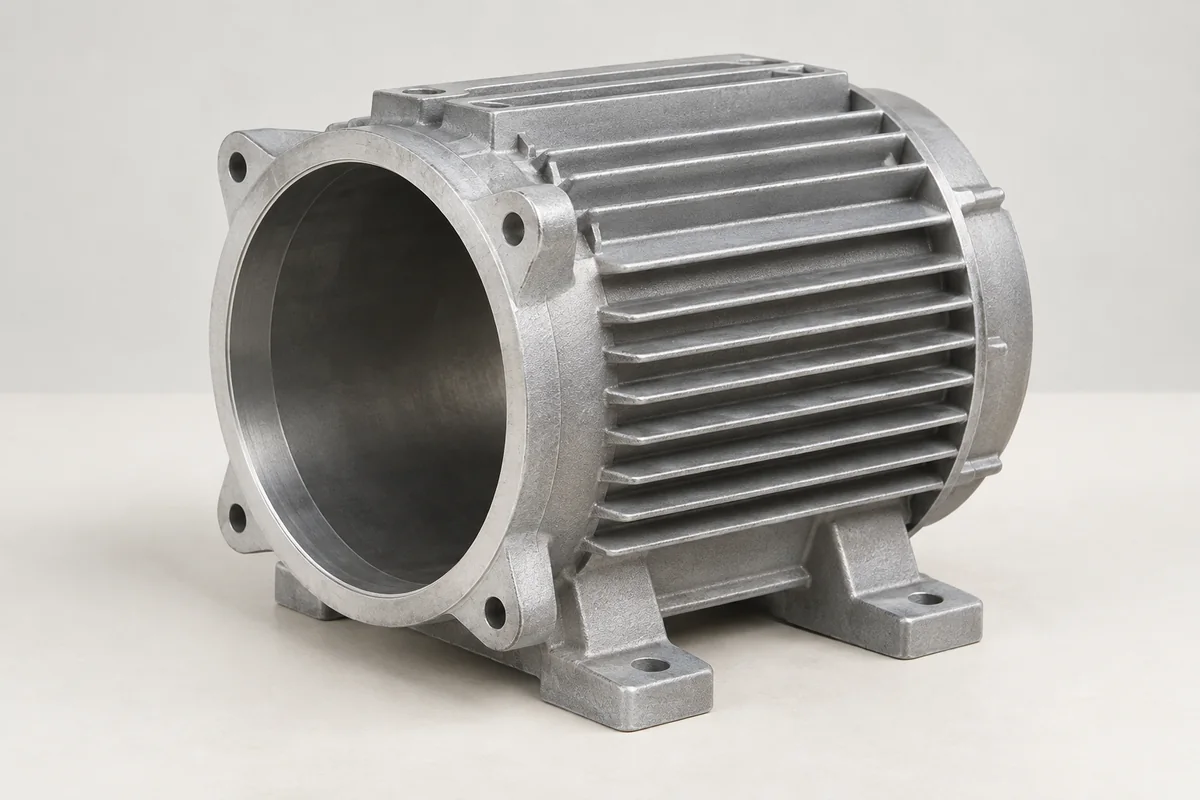
The motor housing holds the stator and connects the end covers to the equipment mount. Its internal geometry must work with the chosen stator retention method, while the exterior may provide cooling fins, feet or a flange. A good review starts with the assembled motor: a housing bore that measures correctly in isolation can still be unsuitable if the end-cover registers or mounting datums are poorly related.
Identify the stator envelope, retention method, axial stop and assembly temperature assumptions. Do not substitute a generic bore tolerance for the fit your motor design needs.
Relate the front and rear locating features to the motor axis. Include the surfaces that establish axial position and the fastening sequence.
Show mounting orientation, access for fasteners and the surrounding airflow space. Fins need practical casting geometry and room for trimming and handling.
Casting · machining · finish
Compare a cast body with an extruded or machined route when the section is substantially constant. Casting becomes useful when feet, flanges, terminal-box features and changing sections must be integrated.
Identify which bore and register features should share a setup or a common datum reference. Machining stock, clamping locations and wall stiffness need to be reviewed together.
Define the exterior coating separately from stator contact areas, grounding points and precision registers. Decide whether final acceptance is before or after finishing.
What can go wrong
These are review points for this type of component. The actual risks depend on the design, process and operating conditions.
A thin body may change shape when clamped or after a tight assembly fit. Discuss measurement support and the condition in which the bore must conform.
Independent machining of both ends without a consistent datum strategy can create a stack-up that affects the rotating assembly.
Fin area alone does not establish heat rejection. Airflow, mounting orientation, motor losses and ambient temperature belong in the system review.
WHAT TO MEASURE ON THIS PART
Use these features to build the inspection scope for your drawing. The illustrated geometry is an example, not a stocked or validated product.
Inspection methods & reporting →| Feature | Requirement to define | Check / evidence |
|---|---|---|
| Stator interface | Bore size, form and texture | Bore and form measurement in the agreed support condition. |
| Cover locations | Relationship of both registers to the datum axis | Coordinate or suitable geometric measurement against the drawing. |
| Mounting features | Foot planes, flange and hole positions | Dimensional report referenced to installation datums. |
| Finished body | Masked contacts, burrs and fin condition | Visual inspection and remeasurement of features affected by finishing. |
Before the quotation
Unknown details can remain open in the first conversation. The next step is to make the assumptions clear.
Yes. A model, photographs or the existing motor envelope can open the discussion. Highlight the stator and end-cover interfaces; unresolved details can be listed for the next review.
The motor designer should establish the fit from the materials, temperature range and retention concept. Manufacturing review can then assess the proposed geometry and acceptance method.
PROCESS, MATERIAL & ACCEPTANCE
Start with what you have
Share a drawing, a few photos or the assembly problem you want to solve. If available, add quantities, material, finish and the interfaces that matter most. These help the review; they do not need to be complete to begin.
Drawing-controlled end caps for motor and equipment assemblies.
Explore this component ↗Gearbox bodies and covers with bearing locations, joint faces and lubricant interfaces reviewed as one assembly.
Explore this component ↗Aluminum mounting components built around equipment interfaces.
Explore this component ↗