CUSTOM ALUMINUM COMPONENTS · CASTING · MACHINING · FINISHINGHave a drawing? Request a quote

Quality / TECHNICAL GUIDE

Leak Testing for Aluminum Castings

Plan leak testing for aluminum pump housings, valve bodies and machined castings. Use the part boundary, test conditions and acceptance limit to define a test that answers your sealing requirement.

Discuss your part ↗

Drawings, sketches, photographs or an early specification are welcome.

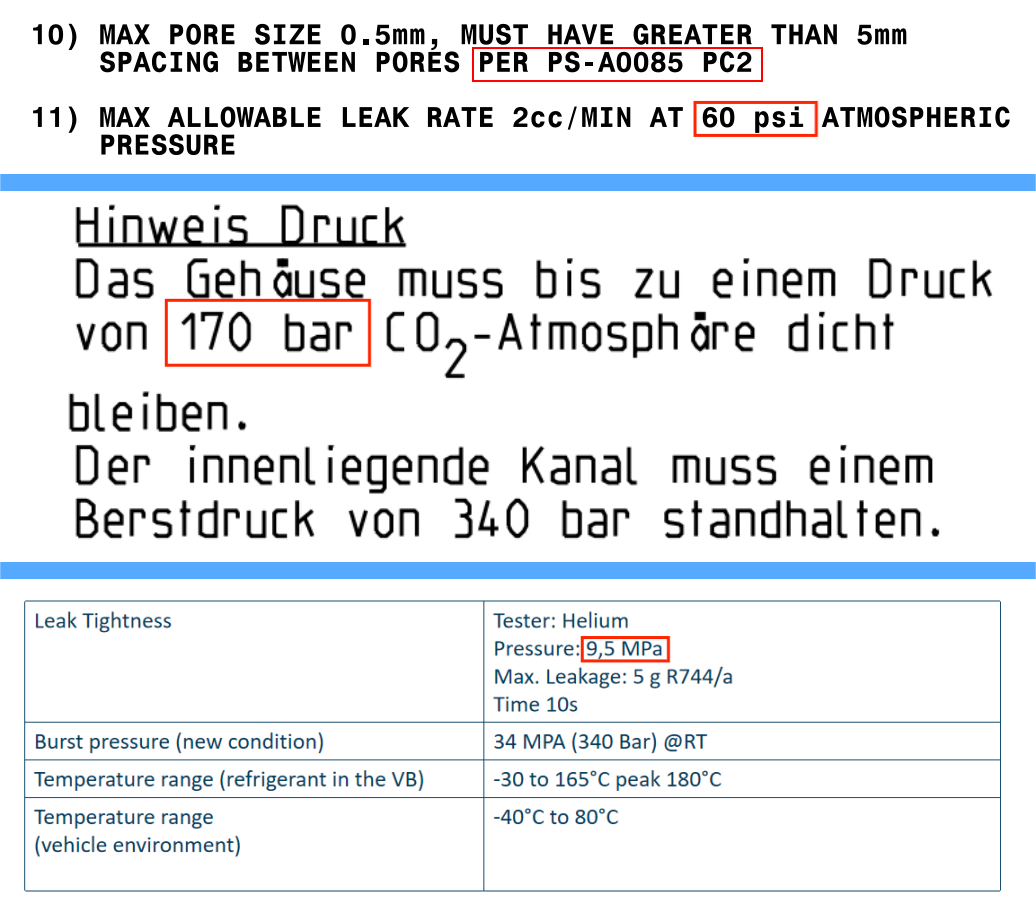
Archived customer specifications showing separate leakage and burst-pressure requirements
Archived customer requirement excerpts. Specifications, not test results or general pressure ratings.

CHOOSING THE INSPECTION

The result applies to the tested part or assembly under the defined conditions. An unassembled casting test does not by itself establish an enclosure IP rating.

READING A REAL SPECIFICATION

A leak limit needs a test definition.

The manufacturing archive includes customer requirement excerpts. They are useful examples of how leakage, test pressure and burst pressure appear on engineering documents.

A limit is not a result

One excerpt specifies a maximum leakage of 2 cc/min and a pressure of 60 psi. Before releasing the test, the full specification must settle the test medium, reference conditions, pressure basis, stabilization and measurement time.

Another excerpt lists helium testing, 9.5 MPa and 10 seconds, with a leakage criterion expressed in grams of R744 per year. The relationship between tracer-gas measurement and that criterion must be defined by the applicable test procedure.

Keep burst and leak tests separate

The archive also includes a 340 bar burst requirement. A burst test and a leakage test answer different questions; one passing result cannot stand in for the other.

The excerpts shown here are customer specifications, not passed test reports or universal factory pressure ratings. Your part's test conditions and acceptance limits are agreed for its application.

What to agree before the first sample

  1. Part and boundary: drawing revision, machining condition, open ports and sealing faces.
  2. Fixture and method: sealing arrangement, medium, test conditions and reference check.
  3. Acceptance: limit with units, measurement interval, sampling and retest rules.
  4. Record: part or lot identification, actual conditions, measured result and disposition.

Confirm the equipment, test location and any third-party work in the quotation. The methods described in this guide are options to review, not a claim that every method is available for every component.

01 / Quality

Define the boundary and fixture

Identify all ports, machined openings and sealing faces. State whether the test applies to the bare casting, finished component or complete assembly. Fixture seals must close the intended openings without masking a region that needs evaluation.

Specify medium, pressure and whether it is gauge or absolute, along with temperature conditions, stabilization, measurement time and rejection threshold with units. If the design is still developing, begin with the working fluid and service conditions so a suitable test can be discussed.

02 / Quality

Match the method to the acceptance question

Pressure-decay testing measures a pressure change over time. Temperature, internal volume, part compliance and fixture leakage influence the result; a pressure-drop value cannot be treated as a universal leak-rate limit across different parts.

Immersion can reveal a leak location through bubbles under specified observation conditions. Tracer-gas testing can support more sensitive leakage evaluation, but gas concentration, background, fixture tightness and a suitable reference check still matter. The methods are not interchangeable solely because each produces a pass/fail result.

03 / Quality

Make a passing result traceable

Check the test system with suitable references and verify fixture condition at the agreed interval. Separate a fixture-seal failure from a component failure, and record how suspect parts are retested.

Retain the part or lot reference, test stage, pressure, duration and result. After a change to machining, coating, sealing hardware or repair condition, review whether the original test remains representative. An immersion check or gas leak result is not a direct prediction of service life.

QUALITY / PROJECT DETAILS

Inspection requirements and records

SubjectTechnical definitionUseful evidence
Pressure decayStable temperature and known test volumePressure/time criterion and recorded conditions
ImmersionDefined pressure and observation coverageBubble criterion, duration and disposition
Tracer gasDefined gas, concentration and test arrangementLeakage units, reference check and result
Complete enclosureGasket, fasteners, entries and assembly stateApplicable assembly ingress validation

The quotation and agreed inspection plan establish which records and checks apply to the project.

COMMON QUESTIONS

Before the specification is complete.

Can you discuss a sealing part without a leak-rate specification?

Yes. Share the working fluid, operating conditions, drawings or photographs and what failure would look like. Those inputs help develop a practical acceptance test.

Does a passed X-ray mean a passed leak test?

No. Imaging and leakage evaluate different attributes. A defined leak test is needed when sealing performance is an acceptance requirement.

RELATED GUIDES

Start with what you have.

Send the part’s purpose, available files and the question you need to resolve. Material, process and inspection details can be developed during the review.

Send an inquiry ↗
VELNOCAST / CONTACT

Send Your Inquiry

Tell us what you need. Drawings or photos are welcome, but not required.

Up to 3 files, 5 MB each. STP, STEP, IGES, IGS, STL, DXF, DWG, PDF, JPG, JPEG, PNG or ZIP.
Add project details (optional)