Seat or cartridge cavity
Identify sealing diameters, shoulders and installation details. A cartridge cavity must follow the selected interface requirements rather than a similar-looking nominal size.
Fluid handling / Custom component supply
Valve and manifold bodies with port connections, internal passages and controlled sealing interfaces.
A drawing, model, sketch or photograph is a useful starting point. Tell us what is known and what still needs work.
The component in service
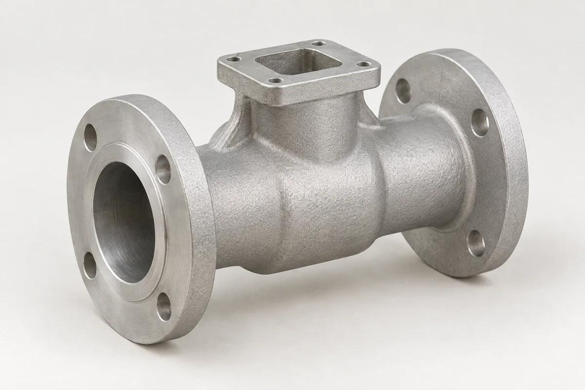
A valve body connects passages and supports the features that control or isolate flow. For some designs the sealing element operates directly against the body; others use an inserted cartridge or seat. That distinction changes the machining, cleaning and inspection scope. Share a circuit sketch or section view alongside the outer model so the intended flow paths are clear.
Identify sealing diameters, shoulders and installation details. A cartridge cavity must follow the selected interface requirements rather than a similar-looking nominal size.
Show which galleries connect and which must stay isolated. Include plugs, breakout locations and access to remove burrs.
State the exact thread or connection specification and where the seal acts. Similar thread sizes can use different sealing arrangements.
Casting · machining · finish
A cast body can integrate mounting geometry and larger cavities; a compact manifold with many precise drilled galleries may also merit a machined billet route. Quantity and passage complexity influence the comparison.
Plan tool access for intersecting passages and the final cleaning sequence. Critical seats may need protection from subsequent drilling or handling.
Specify coating boundaries at cartridge fits, threads and sealing faces. Interior treatment requires a clear purpose and compatibility with the fluid.
What can go wrong
These are review points for this type of component. The actual risks depend on the design, process and operating conditions.
A wall leak test does not establish leakage across a valve seat or between isolated circuits. Name each acceptance boundary.
A small burr or retained chip can interfere with sealing or movement. Hidden intersections deserve more attention than the visible outside finish.
A mismatched thread or seal form can cause assembly problems even when nominal dimensions appear similar. Confirm the full connection designation.
WHAT TO MEASURE ON THIS PART
Use these features to build the inspection scope for your drawing. The illustrated geometry is an example, not a stocked or validated product.
Inspection methods & reporting →| Feature | Requirement to define | Check / evidence |
|---|---|---|
| Seat / cavity | Diameter, depth, texture and edge condition | Feature-specific measurements using the selected interface drawing. |
| Flow circuit | Connected and isolated passage groups | Agreed passage verification and leak checks between required boundaries. |
| Ports and plugs | Thread form, engagement and sealing features | Specified gauges and depth or face checks. |
| Cleanliness | Permitted residual contamination | A documented cleaning and acceptance method proportionate to the application. |
Before the quotation
Unknown details can remain open in the first conversation. The next step is to make the assumptions clear.
An incomplete circuit sketch is a useful start. Mark known ports, the working medium and areas still being developed so the missing information can be resolved.
Body inspection supports dimensional and boundary acceptance. Flow, switching response and seat leakage of the assembled valve require their own agreed validation.
PROCESS, MATERIAL & ACCEPTANCE
Start with what you have
Share a drawing, a few photos or the assembly problem you want to solve. If available, add quantities, material, finish and the interfaces that matter most. These help the review; they do not need to be complete to begin.
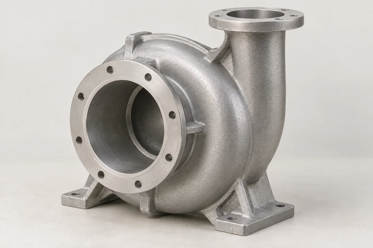
Pump bodies with machined shaft, seal and fluid interfaces, subject to application-specific material and pressure review.
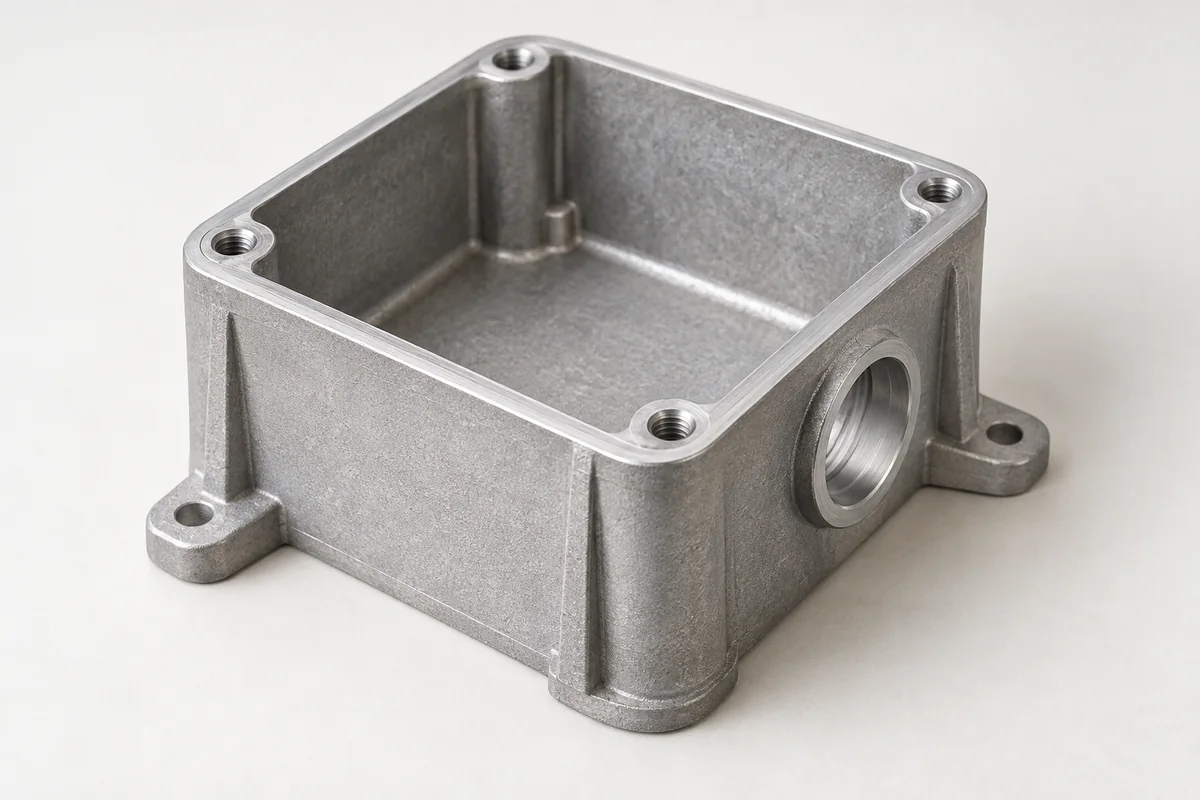
Explore this component ↗Instrument bodies with sensor or display openings, serviceable covers and protected mounting interfaces.
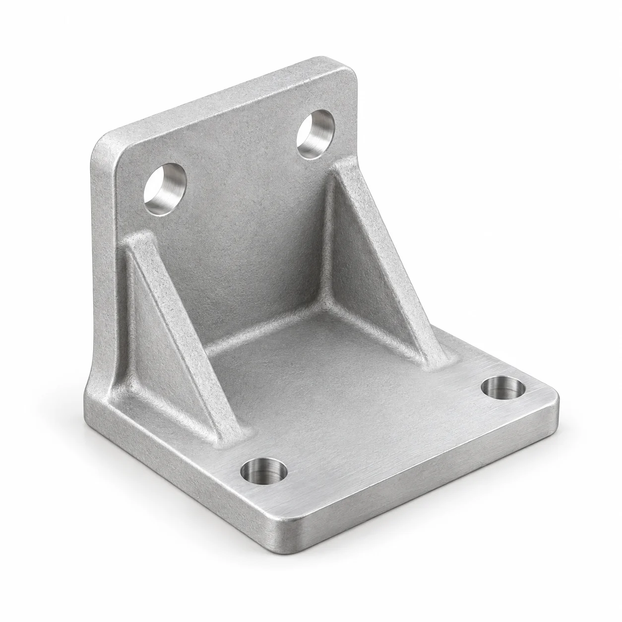
Explore this component ↗Aluminum mounting components built around equipment interfaces.
Explore this component ↗