Heat-source landing
Identify the device or spreader footprint, contact pressure and interface material. Specify flatness and surface texture where they affect the contact arrangement.
Electronics & instruments / Custom component supply
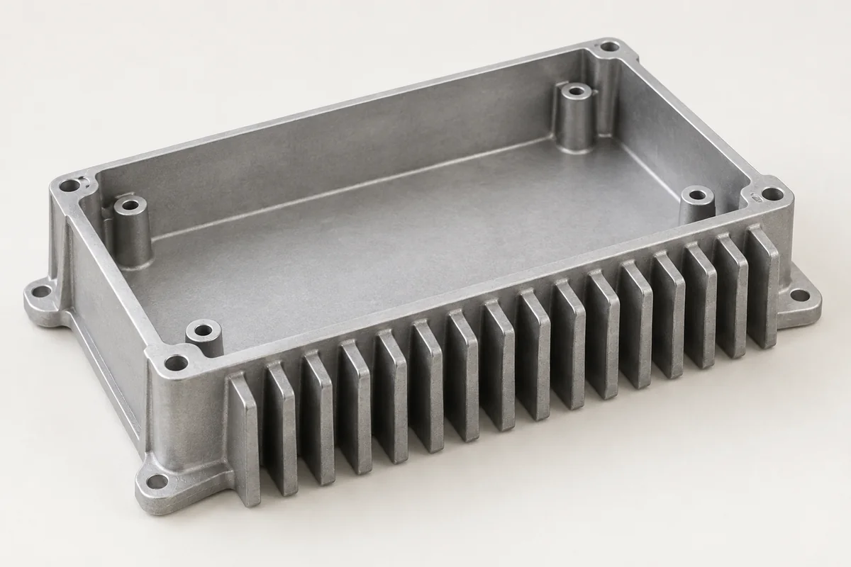
Finned electronic housings that combine component protection, mounting and a defined thermal contact path.
A drawing, model, sketch or photograph is a useful starting point. Tell us what is known and what still needs work.
The component in service
A heatsink housing carries heat from an electronic assembly toward the surrounding air while protecting and locating its components. Thermal contact at the source, fin orientation and available airflow all influence the result. The housing should therefore be reviewed with the heat source and installation envelope, rather than selected by appearance or fin count.
Identify the device or spreader footprint, contact pressure and interface material. Specify flatness and surface texture where they affect the contact arrangement.
Provide installed orientation, nearby obstructions and whether airflow is natural or forced. Fin spacing and height must suit the intended manufacturing route as well as the cooling design.
Keep screw access, PCB clearances and connector paths coordinated with the thermal layout. Confirm any electrical isolation between the heat source and housing.
Casting · machining · finish
A constant fin profile can favor extrusion; changing fin geometry, bosses and integrated enclosure features may favor casting. Machining is another option for prototypes or difficult local features.
The heat-source landing and associated holes may need secondary machining. Define functional surface requirements rather than applying a tight finish requirement to the entire housing.
Treatment affects appearance, corrosion behavior and electrical contact. A coating or dark color does not, by itself, establish a cooling rating; the assembly still needs analysis or testing.
What can go wrong
These are review points for this type of component. The actual risks depend on the design, process and operating conditions.
Poor contact, recirculating air or an obstructed installation can limit performance. Review the full path from device to ambient.
Slender features need a tooling, ejection and handling review. Packaging should protect the geometry that matters to installation and airflow.
Finishing can alter contact at mounting and bonding locations. Identify electrical contact areas before specifying coverage.
WHAT TO MEASURE ON THIS PART
Use these features to build the inspection scope for your drawing. The illustrated geometry is an example, not a stocked or validated product.
Inspection methods & reporting →| Feature | Requirement to define | Check / evidence |
|---|---|---|
| Thermal landing | Flatness, texture and hole pattern | Surface and dimensional checks on the defined contact zone. |
| Fin geometry | Spacing, height and damage limits | Dimensional or visual checks suited to the drawing. |
| Electrical contacts | Masking and contact arrangement | Inspection of finish boundaries; system verification where specified. |
| Thermal result | Power, ambient, airflow and temperature limit | A separate assembly-level thermal analysis or test plan. |
Before the quotation
Unknown details can remain open in the first conversation. The next step is to make the assumptions clear.
A useful rating requires defined operating conditions. Start with the power loss, permitted temperature, ambient and mounting arrangement; estimates can then be tied to explicit assumptions.
Yes. Send those items and identify the main heat sources. A provisional housing concept and the information needed for the next decision can be discussed.
PROCESS, MATERIAL & ACCEPTANCE
Start with what you have
Share a drawing, a few photos or the assembly problem you want to solve. If available, add quantities, material, finish and the interfaces that matter most. These help the review; they do not need to be complete to begin.
Custom aluminum housings for industrial controls and electronic assemblies.
Explore this component ↗Instrument bodies with sensor or display openings, serviceable covers and protected mounting interfaces.
Explore this component ↗Aluminum mounting components built around equipment interfaces.
Explore this component ↗