Inside
Boards and connectors
Provide PCB outline, keep-out zones, mounting locations and connector envelopes. Include assembly clearance, fastener access and any future service requirement.
Industries / Supporting focus
VelnoCast supplies custom aluminum enclosures and mounting components for industrial electronics, with board supports, connector openings, lid interfaces and finish requirements coordinated for your assembly.
AI-generated illustrations of components and processes.
Engineering perspective
Inside
Provide PCB outline, keep-out zones, mounting locations and connector envelopes. Include assembly clearance, fastener access and any future service requirement.
Across the wall
Identify thermal contact areas, interface materials and grounding points. Aluminum alone does not establish thermal performance or electromagnetic compatibility.
At the joint
Coordinate gasket compression, fastener spacing and connector sealing. A target ingress rating requires validation of the complete enclosure assembly.
Engineering perspective
A conductive housing may support an EMC design, but the overall result depends on joints, apertures, cable entries and electrical continuity. Define the areas that require bare metal contact and confirm how the coating and assembly method interact.
Likewise, a fin or a thickened wall does not establish cooling capacity. Provide power dissipation, ambient conditions, mounting orientation and the permitted operating temperature so the appropriate analysis or test can be planned.
Practical answers
An ingress rating must be tied to a defined assembly and test. State the target rating, connector arrangement, gasket design and who is responsible for validating the final assembly.
A coating can interrupt electrical contact. Mark the intended grounding or bonding locations and specify masking or another approved contact arrangement.
Include the board and connector envelope, heat sources, cable access, mounting method and environmental requirements. Identify interfaces that are still provisional.
Technical reference: Engineering center · Inspection planning
Custom component supply
Send your drawing, material, finish and required quantities. We will review the component and prepare the next steps toward a technical and commercial quotation.
WHAT TO MEASURE ON THIS PART
Use these features to build the inspection scope for your drawing. The illustrated geometry is an example, not a stocked or validated product.
Inspection methods & reporting →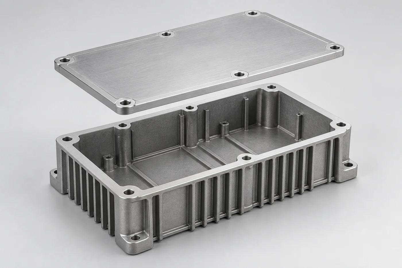
| Feature | Requirement to define | Check / evidence |
|---|---|---|
| Lid / gasket joint | Flatness, surface condition and gasket support geometry. | Dimensional and surface checks to the drawing; inspect damage at the sealing path. |
| Connector openings | Opening position, threads and distance to sealing boundaries. | Datum-based position measurement and specified thread gauges. |
| Enclosure wall | Defined internal-quality zones, especially near ports and machined faces. | Specified porosity evaluation; leak testing is a separate requirement. |
| Finished assembly | Gasket, fasteners, cable entries and assembly condition. | Test the specified assembly configuration; do not infer an IP rating from the casting. |