Protect
Equipment enclosures
Identify the lid joint, cable entries, mounting points and service access. Agree wall and rib geometry around the internal assembly and its expected environment.
Explore the process →Industries / Core focus
VelnoCast supplies aluminum housings, end caps and mounting brackets for industrial equipment. We coordinate casting, functional machining, finishing and inspection to meet the component drawing and assembly requirements.
AI-generated illustrations of components and processes.
Engineering perspective
Protect
Identify the lid joint, cable entries, mounting points and service access. Agree wall and rib geometry around the internal assembly and its expected environment.
Explore the process →Locate
Bearing or shaft interfaces need a considered datum scheme. Specify the relationship between bores, mating faces and fixing patterns rather than treating them as independent dimensions.
Explore the process →Support
Describe the real load direction, fastener arrangement and mating structure. Review section transitions, installation access and any fatigue or vibration validation requirement.
Explore the process →Engineering perspective
State whether the component sees continuous load, vibration, impact, elevated temperature or washdown. If failure would affect safety, identify the applicable design and validation requirements for the complete equipment.
Explain how the part is located, fastened and serviced. A small change in tool access, clearance or datum selection can matter more than an isolated dimensional improvement.
Practical answers
An image is useful for an initial discussion, but it does not establish a safe section size. Load cases, material properties, geometry and validation criteria are needed for a design decision.
Include the fit, bore size, relevant geometric controls, surface condition and the relationship to the mating face. State whether acceptance applies before or after finishing.
Share the current drawing, material, quantity and operating requirements. Identify critical interfaces and the validation your team needs so the technical review can establish a manufacturing and acceptance plan.
Technical reference: Engineering center · Inspection planning
Custom component supply
Send your drawing, material, finish and required quantities. We will review the component and prepare the next steps toward a technical and commercial quotation.
WHAT TO MEASURE ON THIS PART
Use these features to build the inspection scope for your drawing. The illustrated geometry is an example, not a stocked or validated product.
Inspection methods & reporting →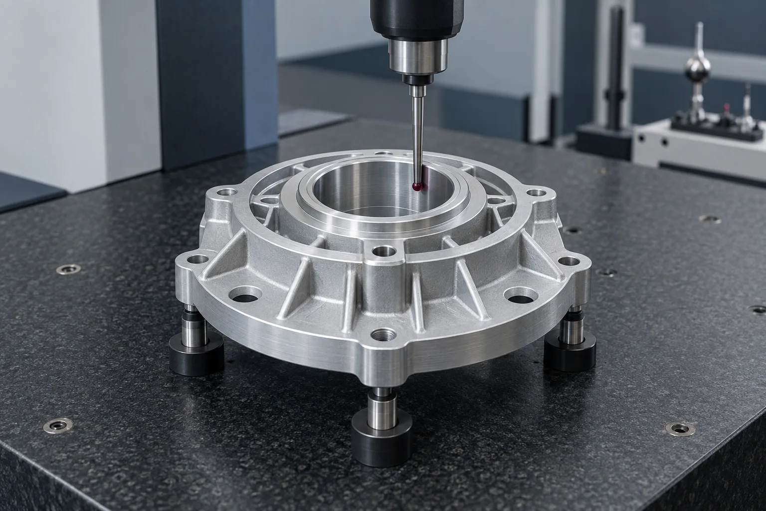
| Feature | Requirement to define | Check / evidence |
|---|---|---|
| Bearing seat | Bore size, form and required surface texture. | Suitable bore measurement, drawing-defined form evaluation and texture check. |
| Flange / bore relationship | Perpendicularity, position or runout as actually specified. | CMM or suitable geometric measurement using the specified datum system. |
| Bolt pattern | Hole size, location, counterbore and fastener clearance. | Coordinate or functional-gauge inspection appropriate to the tolerance. |
| Final condition | Clean bores, burr-free edges and correctly masked fits. | Visual and dimensional checks after operations that can affect acceptance. |