From a part requirement
to a clear supply scope.
Three example briefs show how geometry, manufacturing and acceptance criteria can be brought into one project discussion.
Industrial electronics housing
A cast enclosure with a machined cover interface
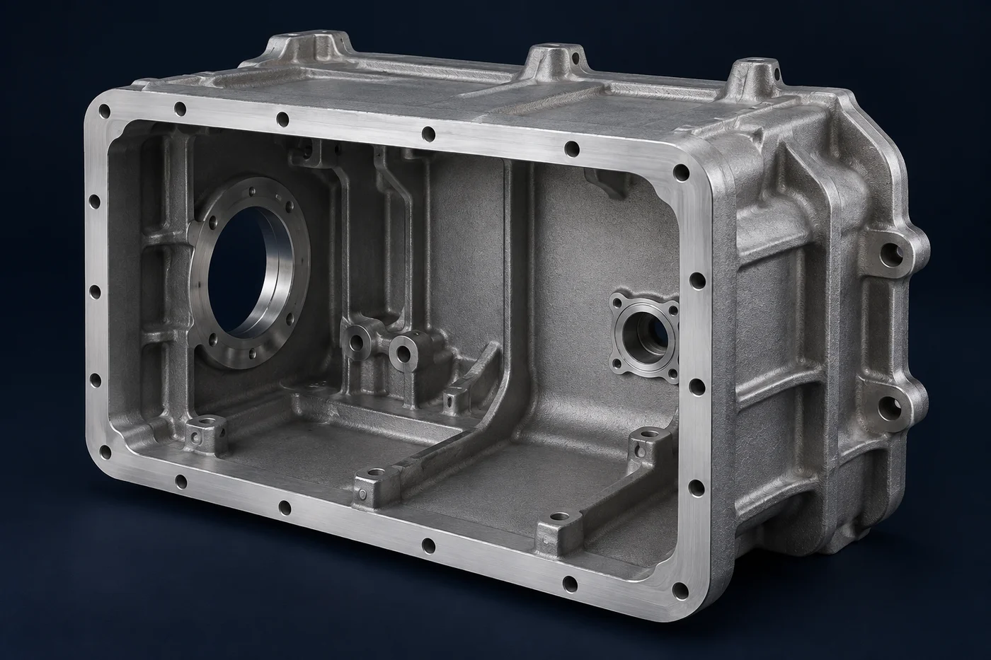
| Material | ADC12 aluminum alloy |
|---|---|
| Envelope | 240 × 180 × 85 mm |
| Initial order | 500 pieces |
| Indicative annual demand | 3,000 pieces |
| Finish concept | Powder-coated exterior; masked interfaces |
The engineering question
The enclosure must accommodate connectors and mounting features while maintaining a defined cover interface. The project review needs to separate cosmetic exterior surfaces from functional surfaces that require machining or masking.
Connect the process steps.
- 01
Review the cover joint, connector openings and fixing access against the proposed casting geometry.
- 02
Evaluate tooling, draft, ribs and machining allowance before finalizing the process.
- 03
Machine the specified interfaces, then apply the agreed finish with controlled masking.
Agree what will be checked.
| Feature / requirement | Review before production |
|---|---|
| Cover interface | Agree datums, flatness and surface condition on the drawing. |
| Connector openings | Check position and size against the current drawing revision. |
| Surface treatment | Agree coating specification, masking boundaries and cosmetic reference. |
| Sealing performance | Define test conditions and acceptance criteria if required by the application. |
A reviewed drawing revision, agreed manufacturing scope, sample approval plan and quotation separating tooling from recurring part supply.
Motor assembly end cap
Bearing location and flange geometry considered together
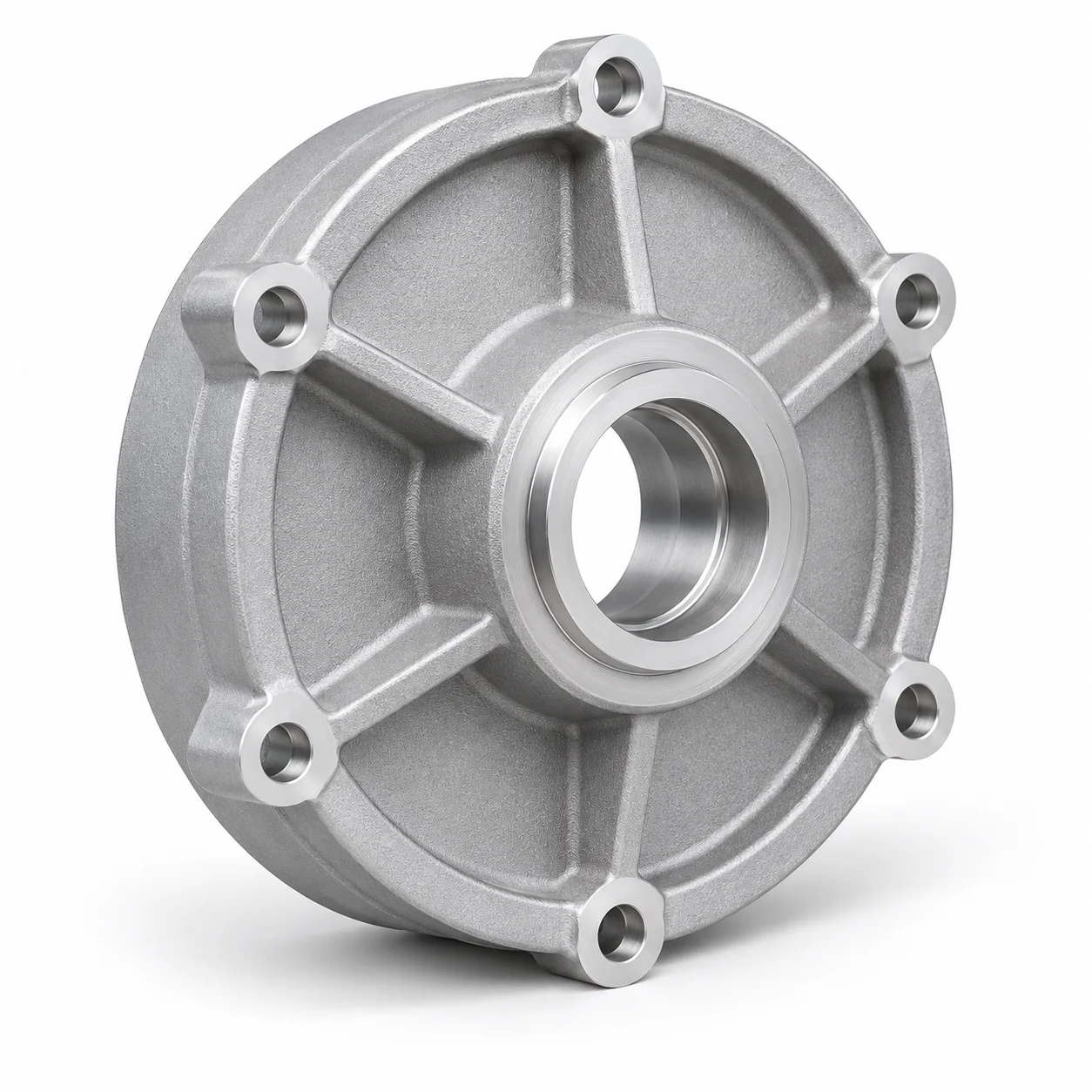
| Material | AlSi9Cu3 aluminum alloy |
|---|---|
| Outer diameter | 160 mm |
| Overall depth | 42 mm |
| Initial order | 800 pieces |
| Indicative annual demand | 5,000 pieces |
The engineering question
The bearing interface and flange must locate the component in the assembly. Machining and inspection need to reference the same functional features, rather than assessing each dimension independently.
Connect the process steps.
- 01
Confirm bearing-seat requirements, axial locating faces and the assembly datum scheme.
- 02
Review the cast geometry and stock allowance for the functional machined features.
- 03
Plan machining and dimensional inspection around the approved references.
Agree what will be checked.
| Feature / requirement | Review before production |
|---|---|
| Bearing bore | Define nominal size, fit requirement, surface finish and measurement method. |
| Flange geometry | Confirm the relationship between the mating face and bearing interface. |
| Fixing pattern | Check drawing-defined hole positions and fastening requirements. |
| Part condition | Agree deburring, cleanliness, protection and packing requirements. |
A drawing-based list of critical characteristics, a proposed casting and machining scope, and an inspection record format for approval.
Equipment mounting bracket
Ribbed geometry with defined mounting pads and fixings
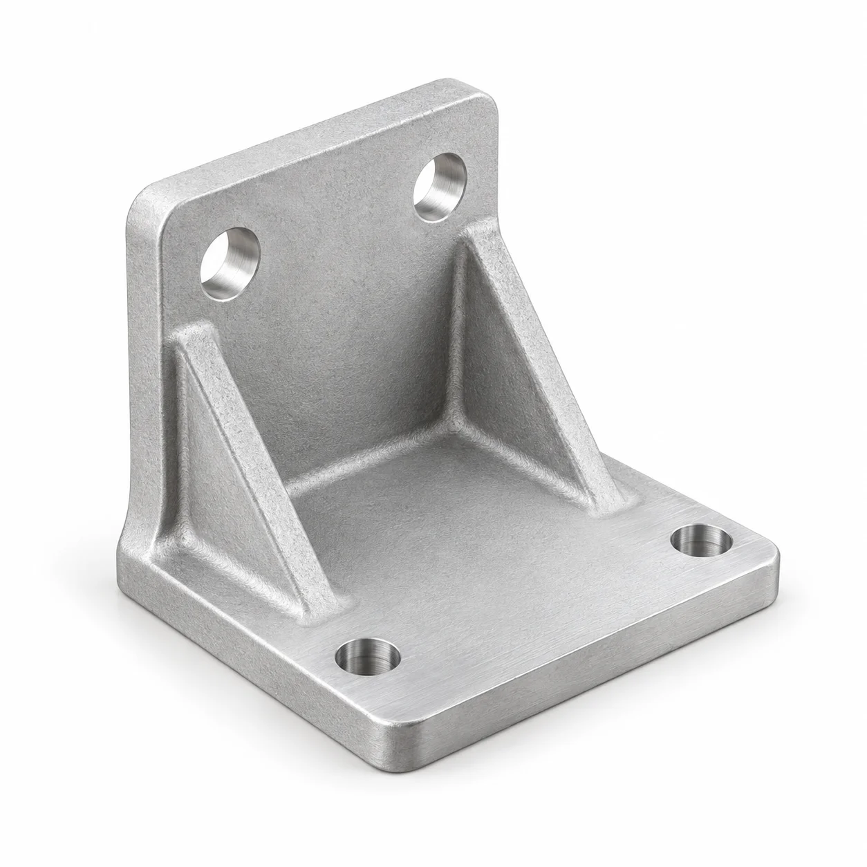
| Material | ADC12 aluminum alloy |
|---|---|
| Envelope | 120 × 85 × 95 mm |
| Initial order | 1,000 pieces |
| Indicative annual demand | 8,000 pieces |
| Finish concept | Powder coating; masked mounting pads |
The engineering question
The bracket connects two assembly surfaces. The review must consider mounting access, rib transitions, hole relationships and the boundary between coated surfaces and functional contact areas.
Connect the process steps.
- 01
Review geometry, rib transitions, draft and available machining access.
- 02
Identify the mounting datums and define the machining scope for pads, holes and threads.
- 03
Agree treatment, masking and final dimensional checks before production planning.
Agree what will be checked.
| Feature / requirement | Review before production |
|---|---|
| Mounting pads | Define functional datums and drawing requirements for the contact faces. |
| Holes and threads | Confirm positions, thread callouts, engagement and inspection approach. |
| Coating boundaries | Agree masked areas, cosmetic criteria and handling protection. |
| Application verification | Identify any load or assembly testing required by the customer specification. |
An agreed finished-part specification covering geometry, machining, coating boundaries and inspection scope, with project-specific commercial terms.
Turn the example into
a project-specific conversation.
Send your drawing, quantity and application requirements. We will review the scope needed for your component.